

Embedded Firmware Flashing Tutorial: Master the MultiNav Pro+ Power/Program Kit
RFOXiA SuperCapacitor Battery and Programmer Kit
Your Complete Embedded Firmware Flashing Tutorial for Professional Wireless Development
If you have ever spent an afternoon hunting down a loose USB cable, fighting a flaky bench power supply, or watching your firmware flash fail mid-transfer because your target board browned out — this guide is for you. This embedded firmware flashing tutorial walks you through everything you need to know about setting up, powering, and programming the RFOXiA MultiNav Pro+ BLE Module using the MultiNav Pro+ Power/Program Kit. By the end, you will have a professional, reliable firmware development workflow that eliminates the most common failure points in embedded hardware development.
Whether you are a drone builder pushing the limits of long-range telemetry, an IoT engineer prototyping sensor networks, or a robotics developer who needs dependable wireless communication, this tutorial will save you hours of troubleshooting and get you shipping firmware with confidence.
What Is the MultiNav Pro+ Power/Program Kit?
Before we dive into the embedded firmware flashing tutorial steps, it helps to understand exactly what this kit is and why it was engineered the way it was.
The RFOXiA SuperCapacitor Battery and Programmer Kit is not a generic power bank with a USB port slapped on the side. It is a purpose-built power and programming solution designed specifically for the MultiNav Pro+ module ecosystem. Two technologies define it:
1. A supercapacitor-based battery system — 1100F total capacitance, storing 8800 Joules of energy. This is enough to power the full MultiNav Pro+ module stack for an entire working day, and it charges completely in under five minutes.
2. An integrated STLink programmer interface — the same interface used in professional embedded development environments, giving you reliable JTAG/SWD access to the STM32WB07 microcontroller at the heart of the BLE Module.
Together, these two systems solve the two biggest problems in embedded firmware work: unstable power during flashing and inconsistent programmer connections. Let us go through each component in detail before walking through the actual firmware flashing process.
Component Deep Dive
The Supercapacitor Battery System
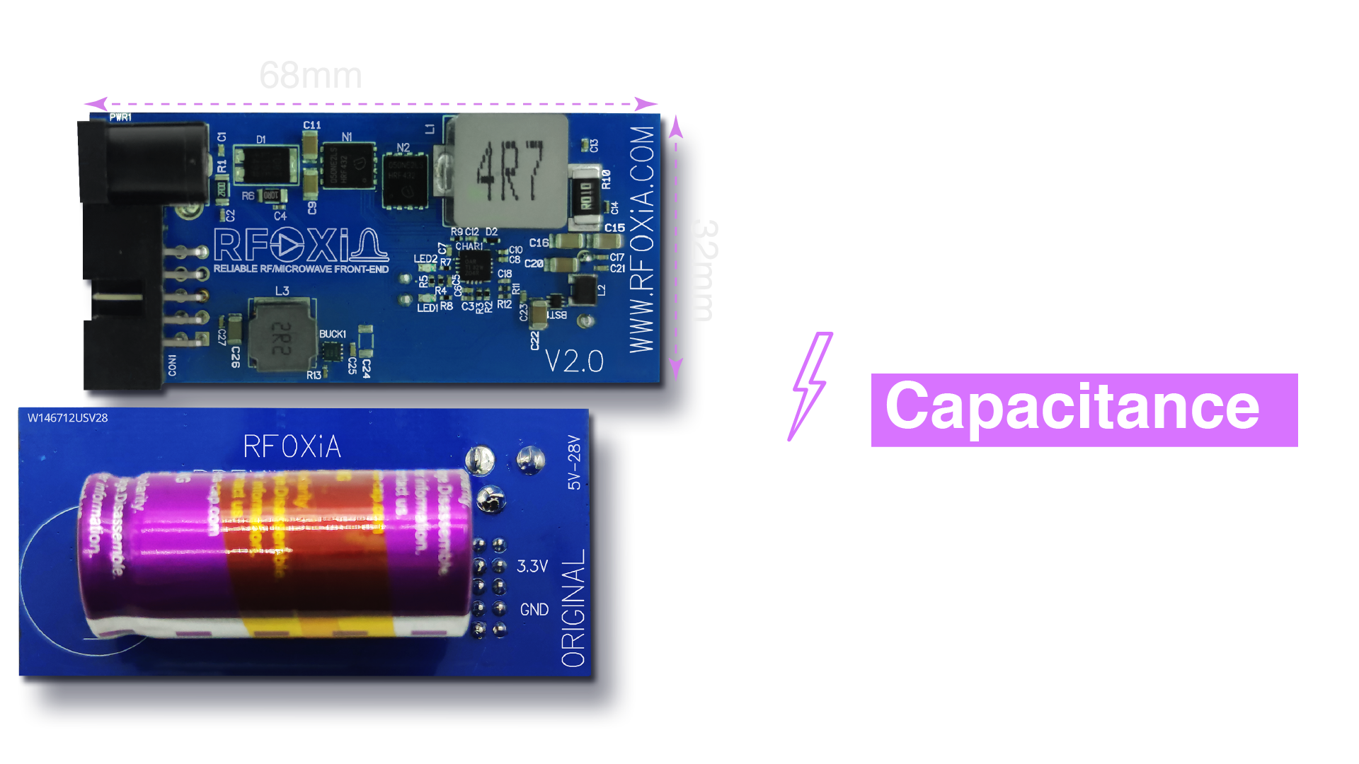
Supercapacitors are fundamentally different from lithium batteries. While a lithium cell stores energy through an electrochemical reaction — a process that takes time and degrades over charge cycles — a supercapacitor stores energy electrostatically. This means charge and discharge rates are dramatically faster, cycle life is measured in hundreds of thousands of cycles rather than a few hundred, and there is no memory effect or capacity fade over time.
For firmware development, the practical benefit is this: you charge the kit for five minutes at the start of your session and work uninterrupted for the rest of the day. No swapping batteries, no voltage sag mid-flash, no unexpected resets from a depleted power source. The 8800 Joules stored in the 1100F system provides a rock-solid supply rail for the BLE Module and all connected peripheral modules throughout a full development day.
This is especially critical during firmware flashing. A voltage drop or supply interruption mid-flash can corrupt the target device's flash memory, sometimes rendering it unresponsive to subsequent programming attempts. With supercapacitor technology, that failure mode is effectively eliminated.
The High-Power Charging Adapter
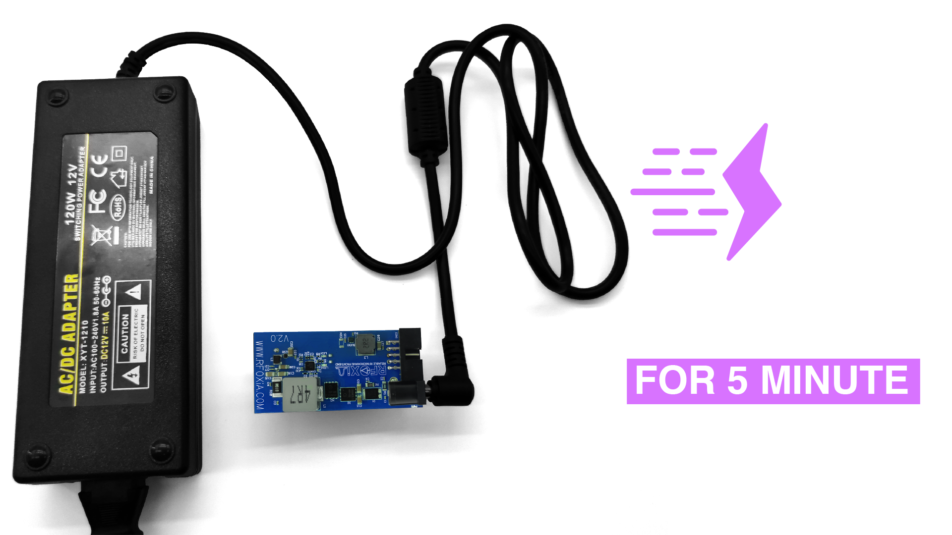
The included 12V 5A adapter feeds a dedicated charging circuit that steps down and delivers 4V at 10A directly into the supercapacitor bank. This high-current charging profile is what achieves the sub-five-minute charge time — something that would be impossible with the trickle-charge approach used for lithium cells.
The adapter is included in the kit and is not optional hardware you need to source separately. Plug it into wall power, connect it to the Power/Program Kit, and within five minutes the system is fully charged and ready for a full day of development.
Full Module Stack Power Output
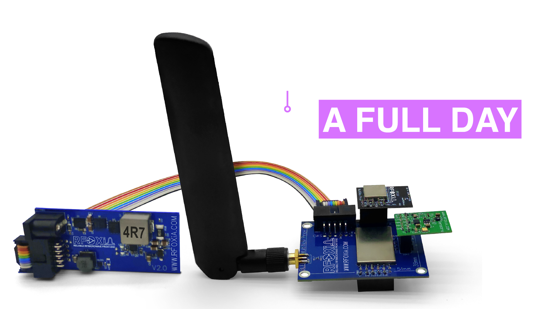
The Power/Program Kit does not just power the BLE Module in isolation. It is designed to supply the entire MultiNav Pro+ ecosystem simultaneously — BLE Module, GNSS Module, and Sensors Module — for a full working day from a single five-minute charge. This is the configuration you will typically use in a complete development or field deployment setup.
For developers building integrated systems that combine long-range wireless, precision GNSS positioning, and multi-parameter environmental sensing, this means you can run and test your complete hardware stack without managing multiple power sources or worrying about which module will brown out first.
The STLink Programmer Interface
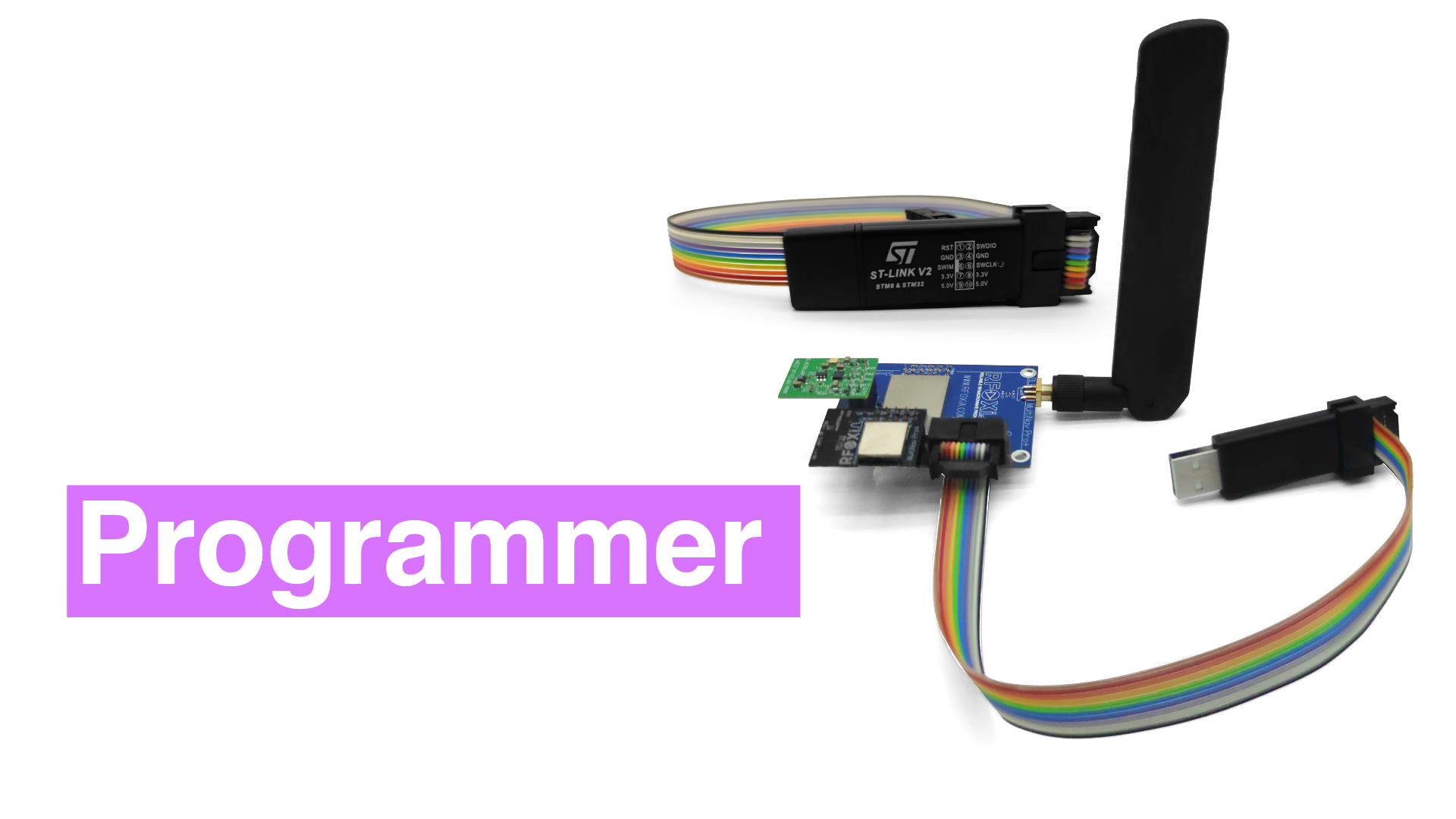
The STLink interface is the centerpiece of this embedded firmware flashing tutorial. STLink is ST Microelectronics' proprietary debug and programming protocol, supporting both JTAG and SWD (Serial Wire Debug) connections. The STM32WB07 at the core of the MultiNav Pro+ BLE Module is fully compatible with STLink, giving you:
- Flash programming: Write firmware binaries directly to the microcontroller's internal flash memory
- Full debug access: Set breakpoints, inspect registers, watch memory in real time using GDB or your IDE's debug view
- Firmware verification: Confirm written firmware matches your binary after flashing
- Mass erase: Clear the entire flash contents when needed
The STLink programmer included in the Power/Program Kit is integrated into the kit's design — it connects via the flat ribbon cable system described below rather than requiring you to manage a separate standalone programmer.
The Complete Connectivity Kit
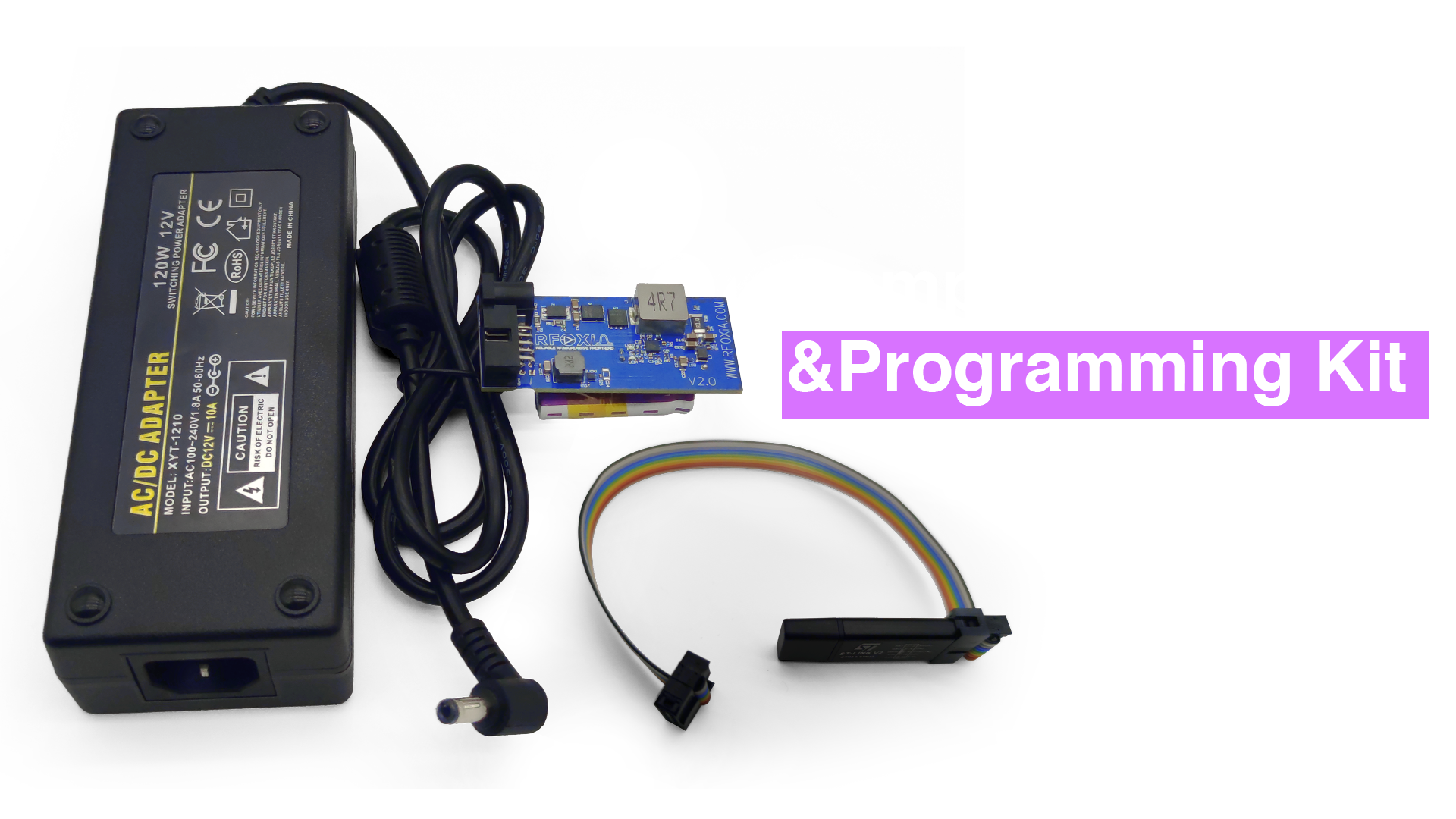
Every cable you need is included. The kit ships with flat ribbon cables that handle two connections:
- BLE Module to Power Module — power delivery from the supercapacitor bank to the BLE Module
- Programmer to BLE Module — STLink SWD connection from the integrated programmer to the BLE Module's debug port
Flat ribbon cables were chosen deliberately. They reduce connection errors compared to individual jumper wires, maintain consistent signal integrity across the SWD lines, and make for a cleaner bench setup. When you are doing repeated firmware flashing during an iterative development cycle, having indexed, keyed connections you cannot accidentally wire backwards is a meaningful quality-of-life improvement.
Embedded Firmware Flashing Tutorial: Step-by-Step
Now that you understand the hardware, here is the full embedded firmware flashing tutorial from initial setup through verified flash.
Prerequisites
Before you start, ensure you have the following:
- MultiNav Pro+ BLE Module
- MultiNav Pro+ Power/Program Kit (fully charged)
- Computer running Windows, macOS, or Linux
- STM32CubeProgrammer installed (free download from ST Microelectronics)
- Your firmware binary (.bin or .hex file) — or clone the open-source firmware from the RFOXiA GitHub repository
- Both flat ribbon cables from the connectivity kit
Step 1: Charge the Power/Program Kit
Connect the 12V 5A charging adapter to the Power/Program Kit's charging input. The onboard indicator will show charging status. Wait for full charge — typically under five minutes from a fully depleted state. Do not skip this step. A partially charged supercapacitor system can still deliver stable voltage, but starting with a full charge gives you the most headroom for long programming sessions.
Step 2: Connect the BLE Module to the Power Module
Using the first flat ribbon cable, connect the BLE Module's power connector to the Power/Program Kit's module output connector. The ribbon cable is indexed — align the key and press firmly until seated. You should feel a positive click. The BLE Module will power on immediately and its status LED will illuminate.
Important: Confirm the BLE Module powers on before connecting the STLink programmer. If the module does not power on, check the ribbon cable seating and verify the kit is charged.
Step 3: Connect the STLink Programmer to the BLE Module
Using the second flat ribbon cable, connect the integrated STLink programmer output to the BLE Module's SWD debug port. Again, align the key on the ribbon cable with the connector housing. This cable carries the SWDCLK, SWDIO, GND, and 3.3V reference lines required for the SWD protocol.
Do not apply excessive force. The connectors are rated for hundreds of insertion cycles, but the contacts are precision-formed and should seat with moderate pressure only.
Step 4: Connect the Kit to Your Computer via USB
The Power/Program Kit includes a USB connection that presents the integrated STLink programmer to your computer as a USB device. Connect a standard USB-A to USB-C (or USB-B, depending on kit revision) cable from the kit to your computer. Your operating system should recognize the STLink device automatically — on Windows you may see a brief driver installation prompt; on macOS and Linux the device typically enumerates without additional drivers.
Step 5: Open STM32CubeProgrammer and Connect
Launch STM32CubeProgrammer on your computer.
- In the connection panel (right side of the interface), set the connection method to ST-LINK
- Set the interface to SWD
- Set the frequency to 4000 kHz (4 MHz) as a starting point — you can increase this for faster programming if your cable runs are short
- Leave NRST connection mode as Connect under reset for the most reliable connection
- Click Connect
If the connection is successful, STM32CubeProgrammer will display the MCU information panel showing the device ID, flash size, and revision for your STM32WB07. This confirms the SWD connection is live and the programmer can communicate with the target.
Common connection errors and fixes:
- No target detected — check ribbon cable seating on both ends, confirm BLE Module is powered on
- Connection timeout — try reducing SWD frequency to 1000 kHz, or enable Connect Under Reset mode
- Target protected — the device may have read-out protection enabled; you can mass-erase via the OB (Option Bytes) tab if you have authorization to do so
Step 6: Load Your Firmware Binary
In STM32CubeProgrammer, navigate to the Erasing & Programming tab (the icon showing a chip with a pencil).
- Click Browse and locate your firmware .bin or .hex file
- Set the Start address — for .bin files this is typically 0x08000000 (the start of flash on STM32 devices); .hex files encode their own address
- Check Verify programming — this is non-negotiable; always verify
- Check Run after programming if you want the firmware to execute immediately after flashing
- Leave Full chip erase unchecked if you want to preserve other flash sectors; check it if you want a clean slate
Step 7: Flash the Firmware
Click Start Programming. STM32CubeProgrammer will:
- Halt the MCU
- Erase the target flash sectors
- Write the firmware binary page by page
- Verify the written data against your source file
- Report success or any errors
A typical firmware binary for the MultiNav Pro+ BLE Module flashes in well under sixty seconds at 4 MHz SWD clock. The supercapacitor power system ensures the target device maintains a clean, stable supply rail throughout the entire sequence — this is where inferior power solutions commonly cause failures.
If programming completes with a green success banner in STM32CubeProgrammer, your firmware is live on the device.
Step 8: Verify and Test
If you selected Run after programming, the BLE Module will restart automatically and begin executing your new firmware. Verify correct operation:
- Check the BLE Module's status LEDs for expected behavior per your firmware's LED logic
- Open a serial terminal (115200 baud, 8N1 is default) via the module's UART interface to check boot messages if your firmware includes them
- Use the RFOXiA Connect app to verify BLE advertisement and pairing if you are flashing communication firmware
For iterative development, you can repeat Steps 6 through 8 as many times as needed without recharging the kit — the supercapacitor system will power the module through many consecutive flash cycles on a single charge.
Using the AI Firmware Builder
If you are not starting from existing source code, RFOXiA Club's integrated AI Firmware Builder can generate production-ready firmware for your specific application. Describe your use case in plain language — "I need firmware that reads from the GNSS module every 100ms and transmits location over BLE to paired mobile devices" — and the AI generates complete, commented, compilable firmware with full source code.
The generated code targets the STM32WB07 and is immediately compatible with the MultiNav Pro+ BLE Module. Compile it using STM32CubeIDE or your preferred ARM toolchain, and use the Power/Program Kit workflow described in this embedded firmware flashing tutorial to flash it to your hardware.
This combination — AI-generated firmware plus professional flashing hardware — compresses what would traditionally be weeks of embedded development into hours.
Why Stable Power Is Non-Negotiable During Firmware Flashing
This embedded firmware flashing tutorial has emphasized power stability repeatedly, and for good reason. Here is what actually happens when power fails during a flash operation:
When the STLink programmer writes firmware, it erases flash pages and then writes new data page by page. If power drops mid-operation, you can end up with:
- Partially erased pages — flash cells that are neither cleanly erased nor written, producing unpredictable reads
- Partial writes — new firmware data in some pages, old data (or garbage) in others
- Corrupted vector table — if the interrupt vector table at address 0x08000000 is not completely written, the device will not boot at all
- Soft-brick states — where the device no longer responds to normal SWD connection attempts without a specific rescue sequence
All of these failure modes are recoverable — STM32 devices are designed with the SWD rescue path in mind — but recovery takes time and interrupts your workflow. The supercapacitor system in the RFOXiA SuperCapacitor Battery and Programmer Kit eliminates this class of failure entirely by delivering a stable, high-current-capable supply rail that does not sag under load.
Comparing the Power/Program Kit to Alternatives
Many embedded developers cobble together their own power and programmer setups from individual components. Here is how the Power/Program Kit compares to the typical alternative:
| Capability | DIY Setup | Power/Program Kit |
|---|---|---|
| Power stability during flash | Variable — depends on supply quality | Rock-solid supercapacitor output |
| Charge time | N/A — battery or bench supply | Under 5 minutes |
| Runtime on full charge | N/A | Full working day |
| Programmer integration | Separate STLink dongle, loose wires | Integrated, ribbon cable connection |
| Portability | Bulky, multiple components | Single compact kit |
| Field deployment readiness | Limited | Yes — 5-minute recharge anywhere |
For developers who work in the field — testing drone telemetry at range, validating sensor deployments outdoors, or iterating firmware in environments without reliable bench power — the kit's portability and recharge speed are uniquely valuable.
Advanced Firmware Development Tips
Use Debug Builds During Development, Release Builds for Deployment
During development, compile your firmware with debug symbols enabled (-g flag in GCC). This allows STM32CubeProgrammer's debug interface, or a GDB server connected through the STLink, to provide full register inspection and breakpoint capability. For production flashing, switch to a release build with optimization enabled for best performance and smaller binary size.
Version Your Firmware Binaries
Establish a naming convention for your .bin files — for example, multinav_v1_2_3_release.bin — and keep all previous versions. If a firmware update introduces a regression, you need to be able to roll back quickly. The Power/Program Kit makes rollback trivial: load the previous binary and flash.
Automate Flashing with STM32CubeProgrammer CLI
For production or batch flashing, STM32CubeProgrammer includes a command-line interface (STM32_Programmer_CLI). You can script the entire connect-erase-program-verify sequence:
STM32_Programmer_CLI -c port=SWD freq=4000 -e all -d firmware.bin 0x08000000 -v -rst
This is especially useful when flashing multiple modules — connect, run the script, disconnect, next module.
Monitor UART Output During Development
Add UART logging to your firmware during development. The MultiNav Pro+ BLE Module exposes UART pins that connect to a standard USB-to-serial adapter. Logging boot state, BLE connection events, and sensor readings to a serial terminal gives you a real-time window into firmware behavior without needing a full debugger attached.
Specifications Summary
| Parameter | Value |
|---|---|
| Supercapacitor Capacitance | 1100F |
| Energy Storage | 8800 Joules |
| Charge Time | Under 5 minutes |
| Runtime (full module stack) | Full working day |
| Charging Input | 12V 5A |
| Charging Output to Supercapacitor | 4V 10A |
| Programmer Interface | STLink (SWD/JTAG) |
| Target MCU Compatibility | STM32WB07 (MultiNav Pro+ BLE Module) |
| Cable Included | Flat ribbon cables (power + programmer) |
| Price | $119 |
| FCC Certification | Yes |
Who Should Get This Kit
The Power/Program Kit is the right choice if any of the following describes you:
- You are actively developing or customizing firmware for the MultiNav Pro+ BLE Module
- You deploy MultiNav Pro+ modules in the field and need a portable power solution
- You are building drones, robots, or remote sensing platforms that need dependable wireless modules
- You are tired of bench supply instability causing firmware flash failures
- You want a single kit that handles both power and programming rather than managing multiple components
If you are just getting started with the MultiNav Pro+ ecosystem, the Developer Bundle — which combines the BLE Module, GNSS Module, Sensors Module, and Power/Program Kit — is the fastest path to a complete working platform.
Get the Power/Program Kit
This embedded firmware flashing tutorial has covered everything from the physics of supercapacitor charging to the step-by-step STLink programming workflow. The hardware that makes all of it possible is the RFOXiA SuperCapacitor Battery and Programmer Kit — available now at $119 with FCC certification, integrated STLink programmer, and all cables included.
Join RFOXiA Club free to access the AI Firmware Builder, download open-source firmware examples from GitHub, and connect with a growing community of drone builders, IoT engineers, and wireless developers who are using the MultiNav Pro+ platform to build things that were previously out of reach.
Your $10 welcome credit is waiting at signup — link in bio.
RFOXiA — Democratizing Connectivity and Computing Power.
Written by: Moamen Mohamed LinkedIn