
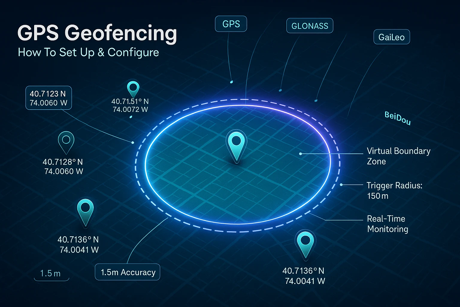
GPS Geofencing Module How To: Build Precise Geofences With the MultiNav Pro+
GPS Geofencing Module How To: Everything Developers Need to Know
Geofencing is one of the most powerful and versatile tools in modern embedded development. Whether you are building a drone that automatically returns home when it drifts beyond a defined boundary, a fleet tracking system that alerts dispatch when a vehicle leaves an approved route, or a smart agriculture platform that triggers irrigation only within specific field coordinates — geofencing is the logic layer that makes location-aware systems intelligent.
But here is the problem most developers run into fast: geofencing is only as good as the GPS data feeding it.
If your GNSS module delivers 5-meter or 10-meter accuracy, your geofence boundary has to be fat and forgiving to avoid false triggers. Your drone might cross a real fence line before your module even registers the event. Your vehicle tracking system fires alerts 30 seconds late. Your precision agriculture system waters the wrong zone.
This guide is a complete walkthrough of the GPS geofencing module how to — from the hardware selection decisions that actually matter, through coordinate math, firmware implementation patterns, real-world use cases, and how to get reliable sub-2-meter geofencing working in production applications.
Throughout this guide, we will use the RFOXiA MultiNav Pro+ as our reference hardware, because at 1.5-meter accuracy and an 18Hz fix rate, it sets a realistic performance ceiling that most developers never get close to with commodity GNSS modules.
Why Your GNSS Module Choice Defines Your Geofence Quality
Before writing a single line of geofencing code, the most important decision you will make is which GNSS module you use. This is not marketing — it is math.
Geofencing works by comparing the device's current GPS coordinates against a defined boundary polygon or radius. When the device crosses that boundary, a trigger fires. The precision of that comparison is directly limited by the accuracy of your incoming position data.
A module with 5-meter circular error probable (CEP) means your reported position could be anywhere within a 5-meter radius of your true location at any given moment. If you define a geofence boundary and your module has 5-meter accuracy, you need to add at least 5 meters of buffer to every boundary edge just to avoid spurious triggers from GPS noise — not from actual movement.
For tight applications — indoor-adjacent deployments, precision agriculture field boundaries, drone no-fly zones near structures — that 5-meter uncertainty is the difference between a working system and one that generates false positives constantly.
The MultiNav Pro+ is built around the u-blox MIA-M10Q chipset, which supports concurrent reception from GPS, GLONASS, Galileo, and BeiDou simultaneously. Receiving from four satellite constellations at once dramatically improves fix geometry, reduces the impact of satellite obstruction, and pushes accuracy down to the 1.5-meter range in open-sky conditions.
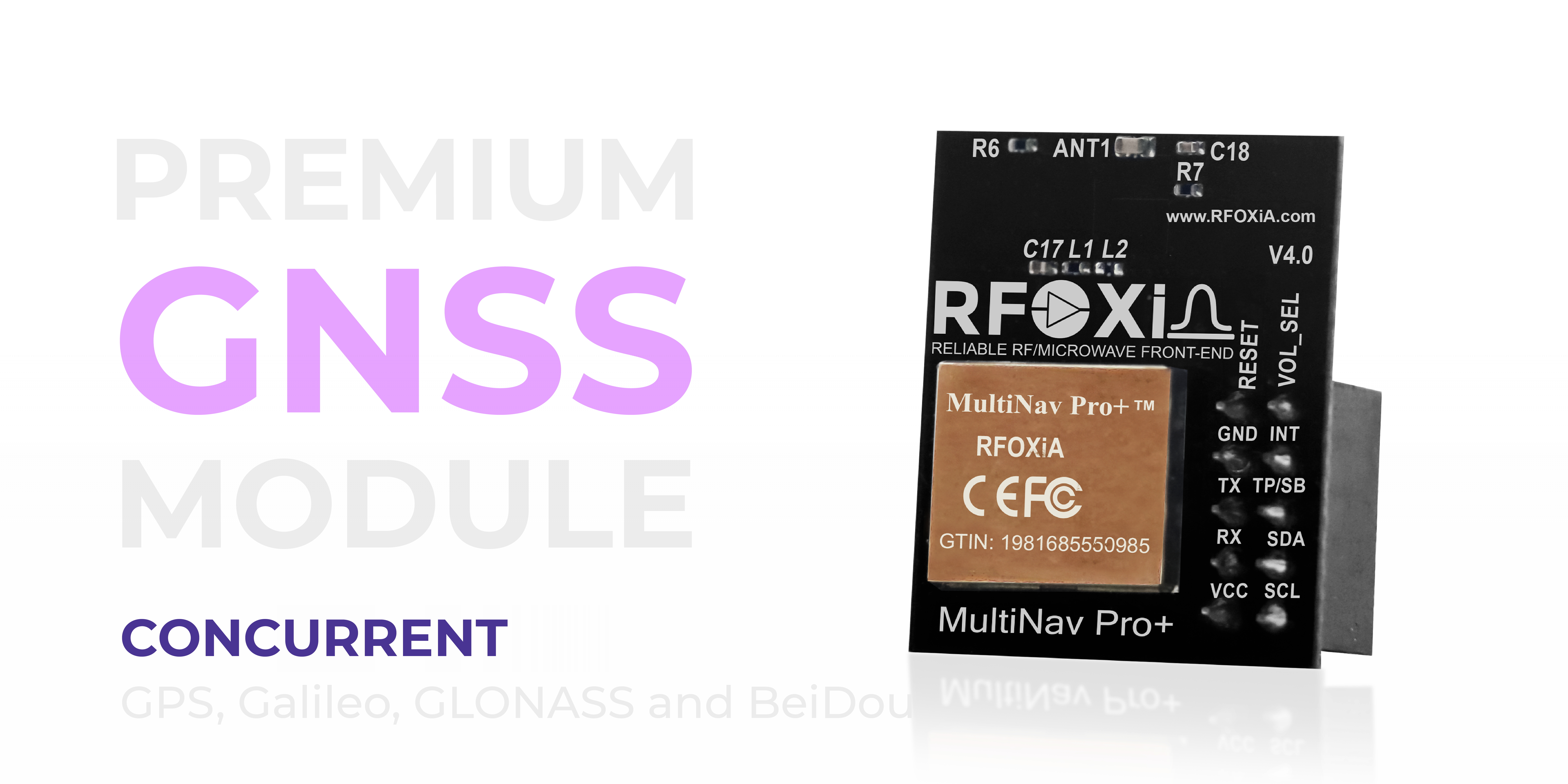
At 1.5-meter accuracy, your geofence buffer shrinks from 5+ meters to under 2 meters. For drone applications, that is the difference between triggering a return-to-home 10 meters before a boundary or triggering it 2 meters before. For precision agriculture, it means your field zone definitions actually correspond to your physical field edges.
Understanding the 18Hz Fix Rate for Geofencing Applications
Accuracy matters enormously, but so does update rate — and this is where many developers underestimate their requirements until they are in the field.
A standard GNSS module at 1Hz updates your position once per second. A drone flying at 10 meters per second covers 10 meters between position updates. If your geofence trigger logic runs at 1Hz, the drone can overshoot a boundary by a full 10 meters before the next position check even fires.
The MultiNav Pro+ operates at 18Hz — 18 position fixes per second. At the same 10 m/s drone speed, the module updates every 0.55 meters of travel. Your geofence trigger fires within less than 1 meter of the actual boundary crossing, even at speed.
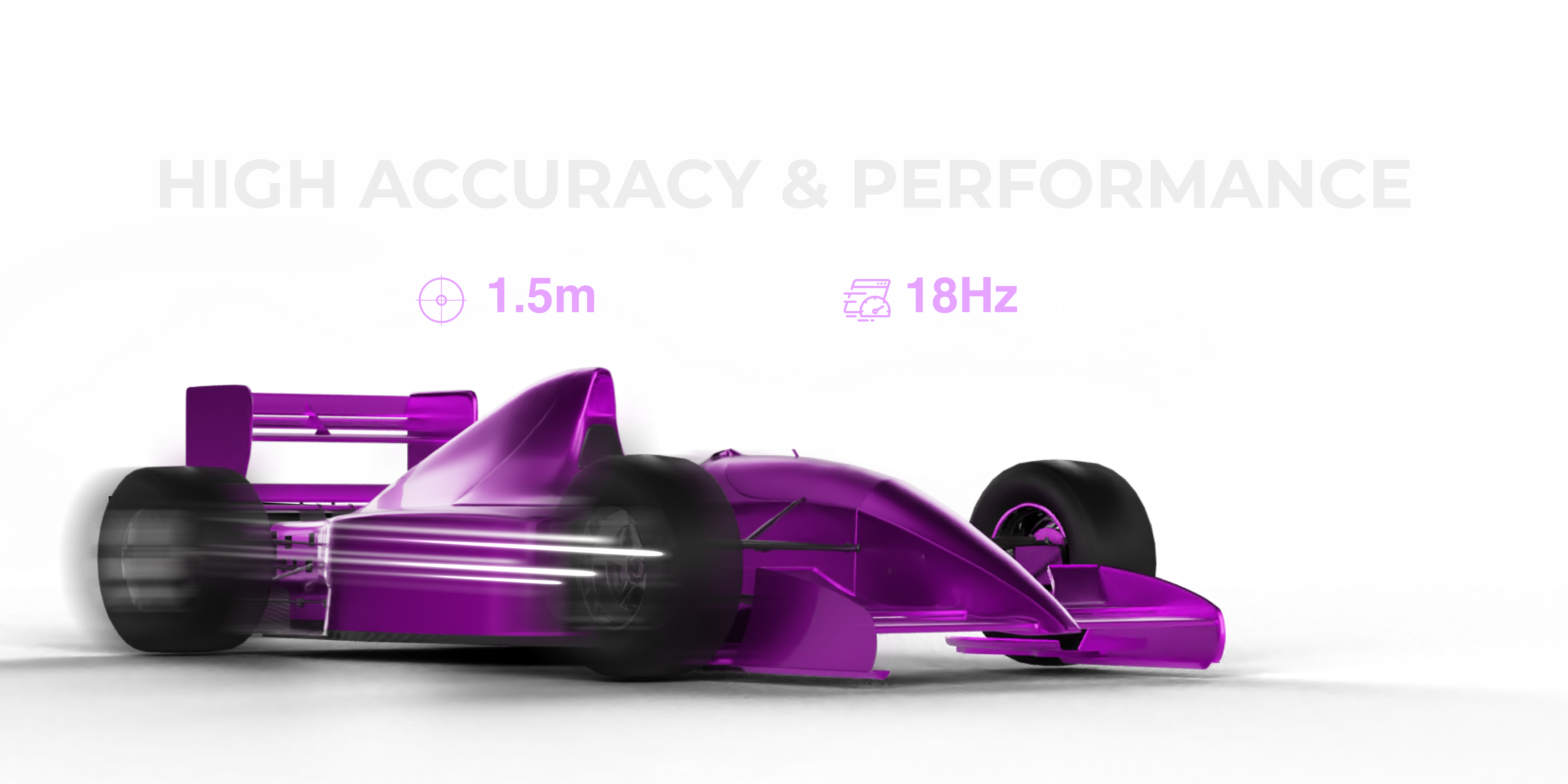
For any moving platform application — drones, vehicles, robots, wearables — the fix rate is not a luxury specification. It is a safety and functionality requirement. Pair 18Hz updates with 1.5-meter accuracy and you have a GNSS foundation that makes tight geofencing genuinely viable on fast-moving platforms.
The first fix in 1 second also matters for deployments where systems start up in the field and need immediate position awareness. You are not waiting 30-60 seconds for a cold start fix before your geofence logic can activate.
Hardware Setup: Connecting the MultiNav Pro+ for Geofencing Projects
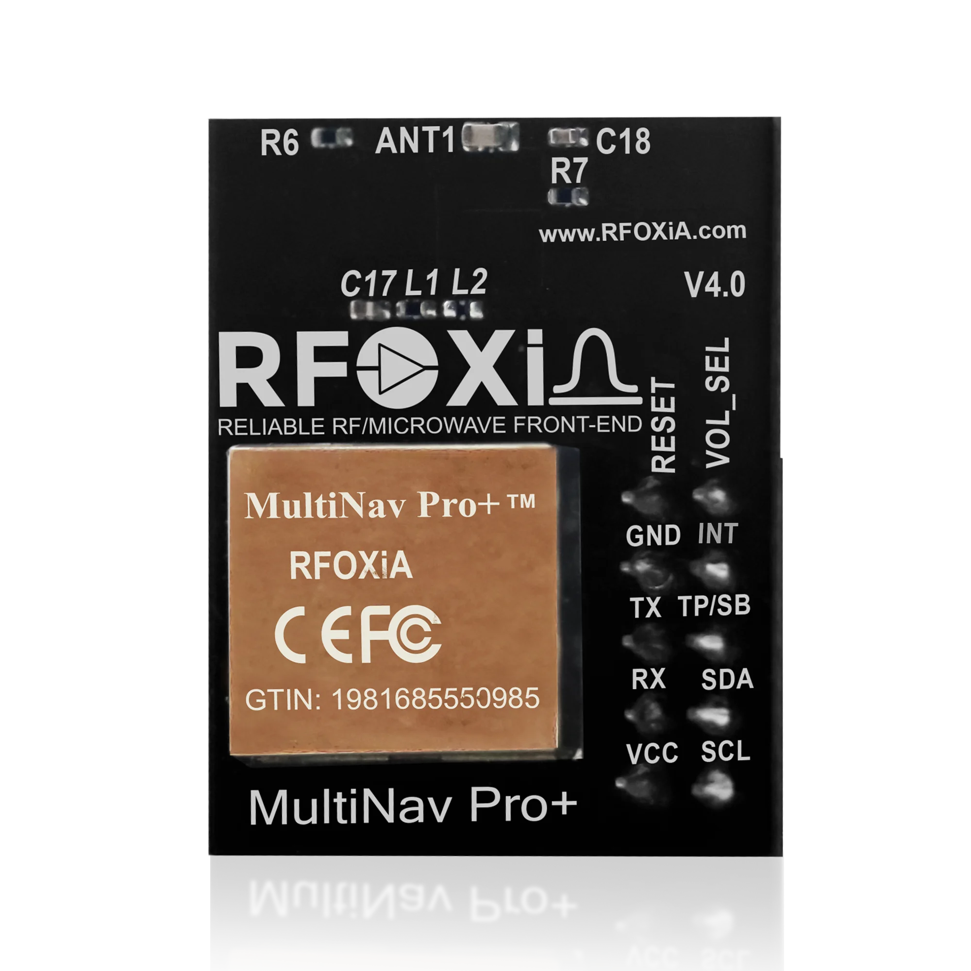
Before getting into firmware, here is the physical integration. The MultiNav Pro+ is compact at 26mm x 22mm and draws only 25-30mA during active multi-constellation tracking — making it practical for battery-powered field deployments and drone integration where power budget matters.
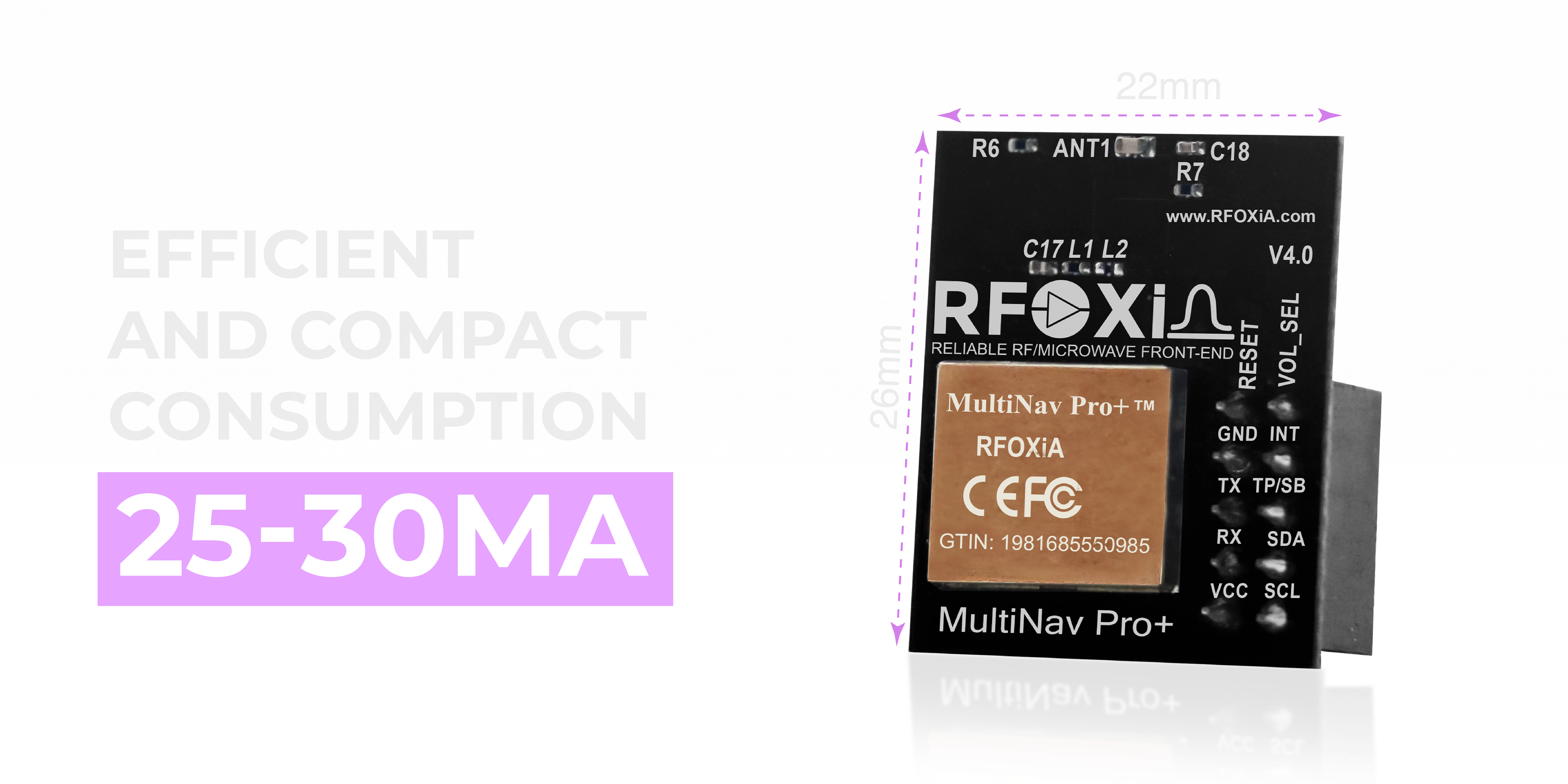
The module supports two interface modes:
UART interface — connect TX and RX pins to your microcontroller's hardware serial port. This is the most common configuration for Arduino, STM32, ESP32, and Raspberry Pi applications. NMEA sentences stream continuously at your configured baud rate.
I2C interface — connect SCL and SDA pins to your I2C bus. Useful when UART ports are occupied or when you want to read position data on demand rather than parsing a continuous stream.
Operating voltage is flexible at 1.8V or 3.3V logic, covering the full range of modern microcontrollers without level shifting in most configurations.
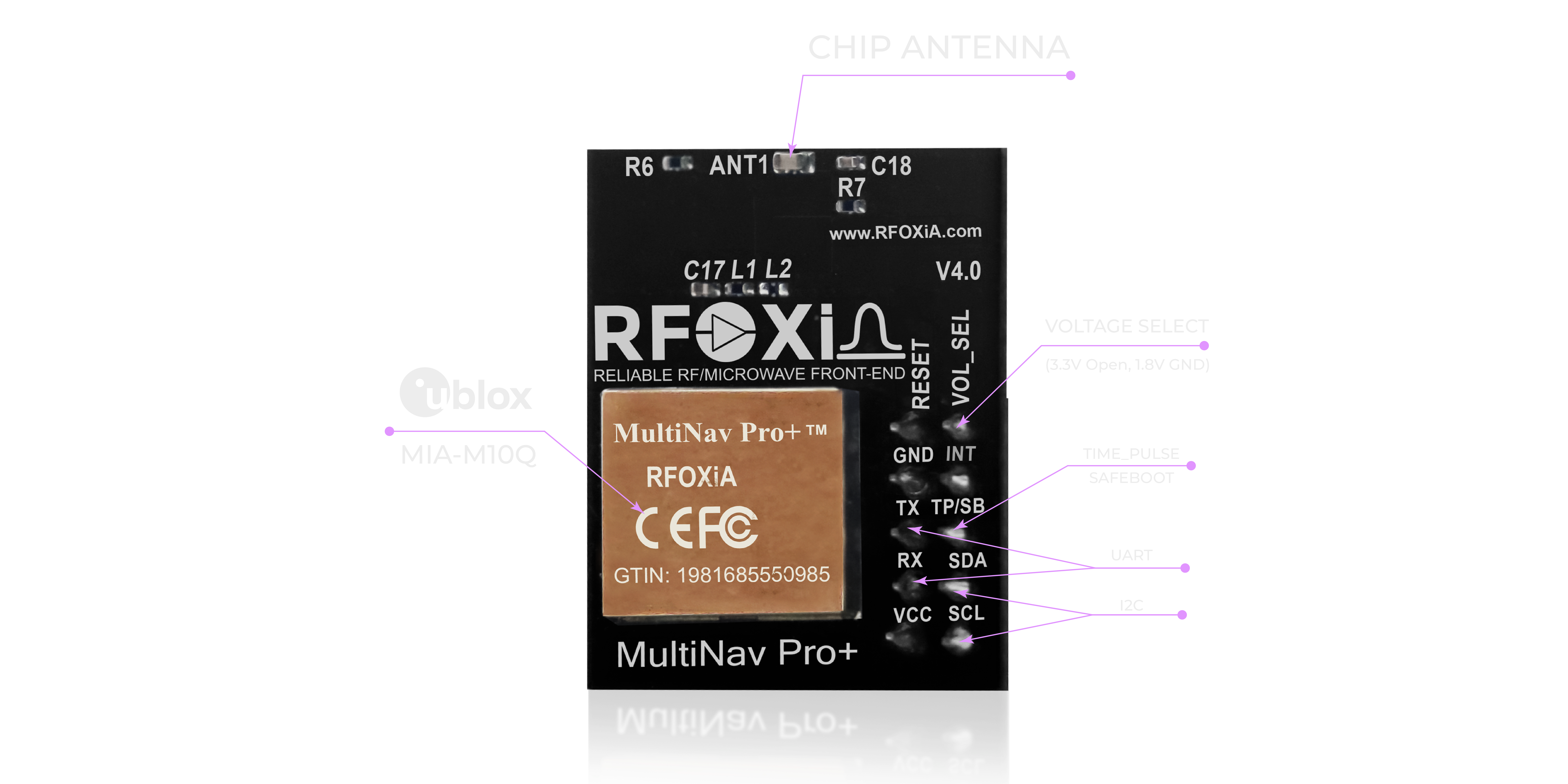
For geofencing applications, UART is generally recommended because it gives you a continuous position stream at full 18Hz update rate. I2C polling at application-level intervals may introduce latency that reduces the effective update rate below what the hardware supports.
Firmware Fundamentals: The GPS Geofencing Module How To in Code
With hardware connected, here is the firmware implementation pattern for a GPS geofencing module how to that actually works reliably in production.
Step 1 — Parse NMEA Data
The MultiNav Pro+ streams standard NMEA 0183 sentences over UART. For geofencing, you primarily need the GNGGA or GNRMC sentence, which contains:
- Latitude (degrees + decimal minutes)
- Longitude (degrees + decimal minutes)
- Fix quality indicator
- Number of satellites in use
- Horizontal dilution of precision (HDOP)
- Altitude
The open-source C library included with the MultiNav Pro+ handles NMEA parsing for you. It is compatible with Arduino IDE and any standard C toolchain, so you are not writing parsing code from scratch.
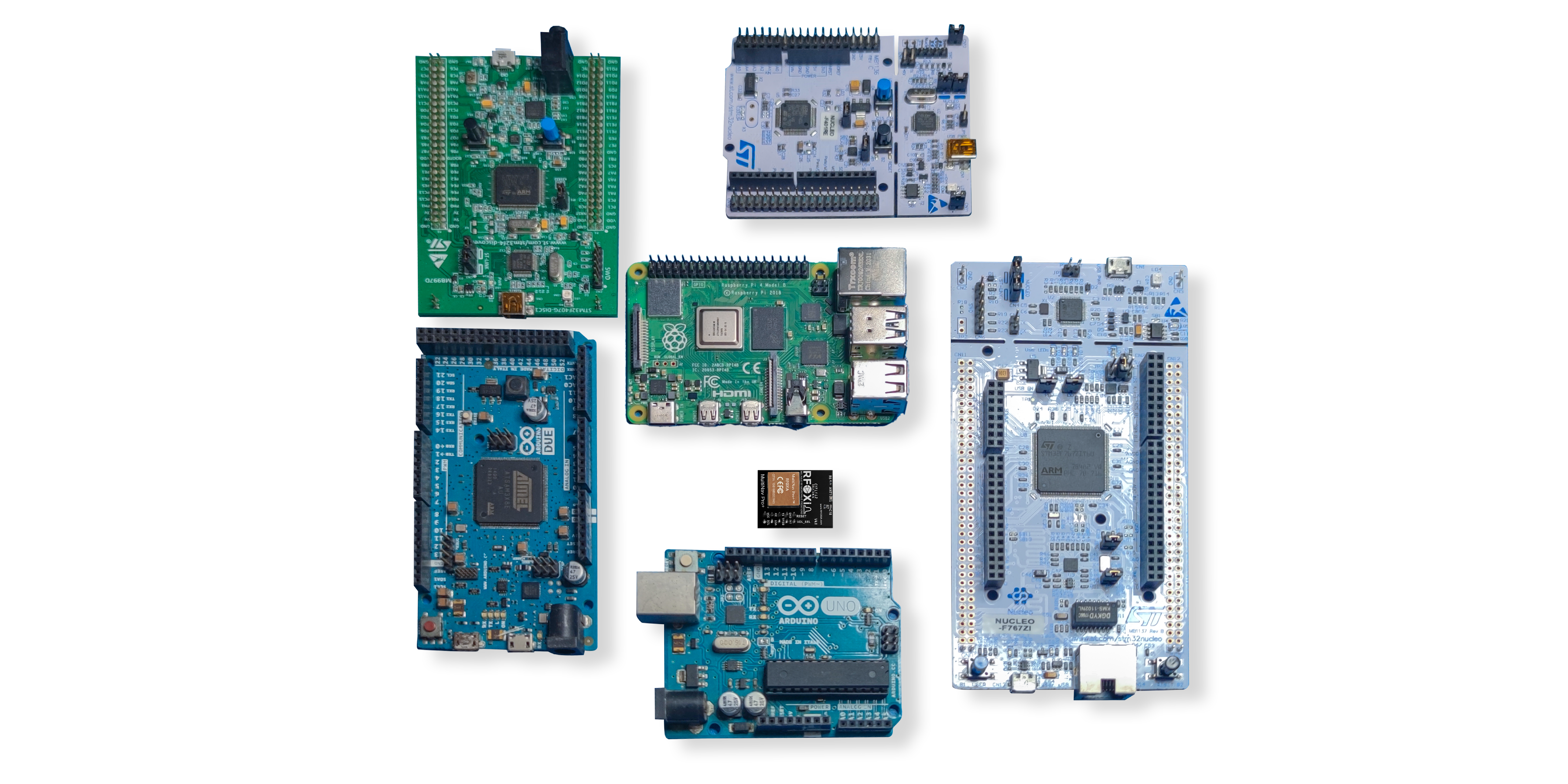
Import the library, initialize the serial port at the configured baud rate, and your application receives structured position objects with every fix.
Step 2 — Convert to Decimal Degrees
NMEA coordinates arrive in degrees-decimal-minutes (DDM) format. Before any geofencing math, convert to decimal degrees (DD):
DD = Degrees + (Minutes / 60)
For a coordinate like 4007.3825 N:
- Degrees = 40
- Minutes = 07.3825
- DD = 40 + (7.3825 / 60) = 40.12304167
West longitudes and South latitudes are negative in DD format.
Step 3 — Implement the Haversine Distance Formula
The core of any circular geofence is distance calculation between two geographic coordinates. Because the Earth is spherical, flat-plane Euclidean distance does not work at meaningful scales. The haversine formula gives great-circle distance:
double haversine(double lat1, double lon1, double lat2, double lon2) {
    double R = 6371000.0; // Earth radius in meters
    double phi1 = lat1 * M_PI / 180.0;
    double phi2 = lat2 * M_PI / 180.0;
    double dphi = (lat2 - lat1) * M_PI / 180.0;
    double dlambda = (lon2 - lon1) * M_PI / 180.0;
    double a = sin(dphi/2)*sin(dphi/2) +
               cos(phi1)*cos(phi2)*
               sin(dlambda/2)*sin(dlambda/2);
    double c = 2 * atan2(sqrt(a), sqrt(1-a));
    return R * c; // Distance in meters
}
With this function, your geofence check becomes:
double distance = haversine(current_lat, current_lon, fence_center_lat, fence_center_lon);
if (distance > fence_radius_meters) {
    trigger_geofence_event();
}
For polygon geofences rather than circular zones, implement a point-in-polygon algorithm (ray casting is standard). Define your polygon as an array of lat/lon vertex pairs and test whether the current position lies inside or outside.
Step 4 — Filter by Fix Quality
Do not run geofence checks on poor-quality fixes. Check HDOP before triggering:
if (gnss_data.hdop < 2.0 && gnss_data.fix_quality >= 1 && gnss_data.satellites >= 4) {
    // Run geofence check
}
HDOP below 2.0 indicates good satellite geometry. Below 1.0 is excellent. Filtering bad fixes prevents false geofence triggers from momentary satellite loss or obstruction.
Step 5 — Add Hysteresis to Prevent Boundary Oscillation
When a device sits near a geofence boundary, position noise can cause rapid inside/outside state flipping — triggering dozens of events per second. Hysteresis fixes this:
#define FENCE_OUTER_RADIUS 100.0  // Triggers exit at 100m
#define FENCE_INNER_RADIUS 90.0   // Re-enters at 90m

if (!outside_fence && distance > FENCE_OUTER_RADIUS) {
    outside_fence = true;
    trigger_exit_event();
} else if (outside_fence && distance < FENCE_INNER_RADIUS) {
    outside_fence = false;
    trigger_enter_event();
}
The 10-meter hysteresis band prevents oscillation while keeping trigger response tight relative to your boundary.
Using u-Center Software for Geofencing Configuration and Validation
Before deploying to production, validate your GNSS module configuration and accuracy using u-Center — the desktop GUI application from u-blox that interfaces directly with the MIA-M10Q chip inside the MultiNav Pro+.
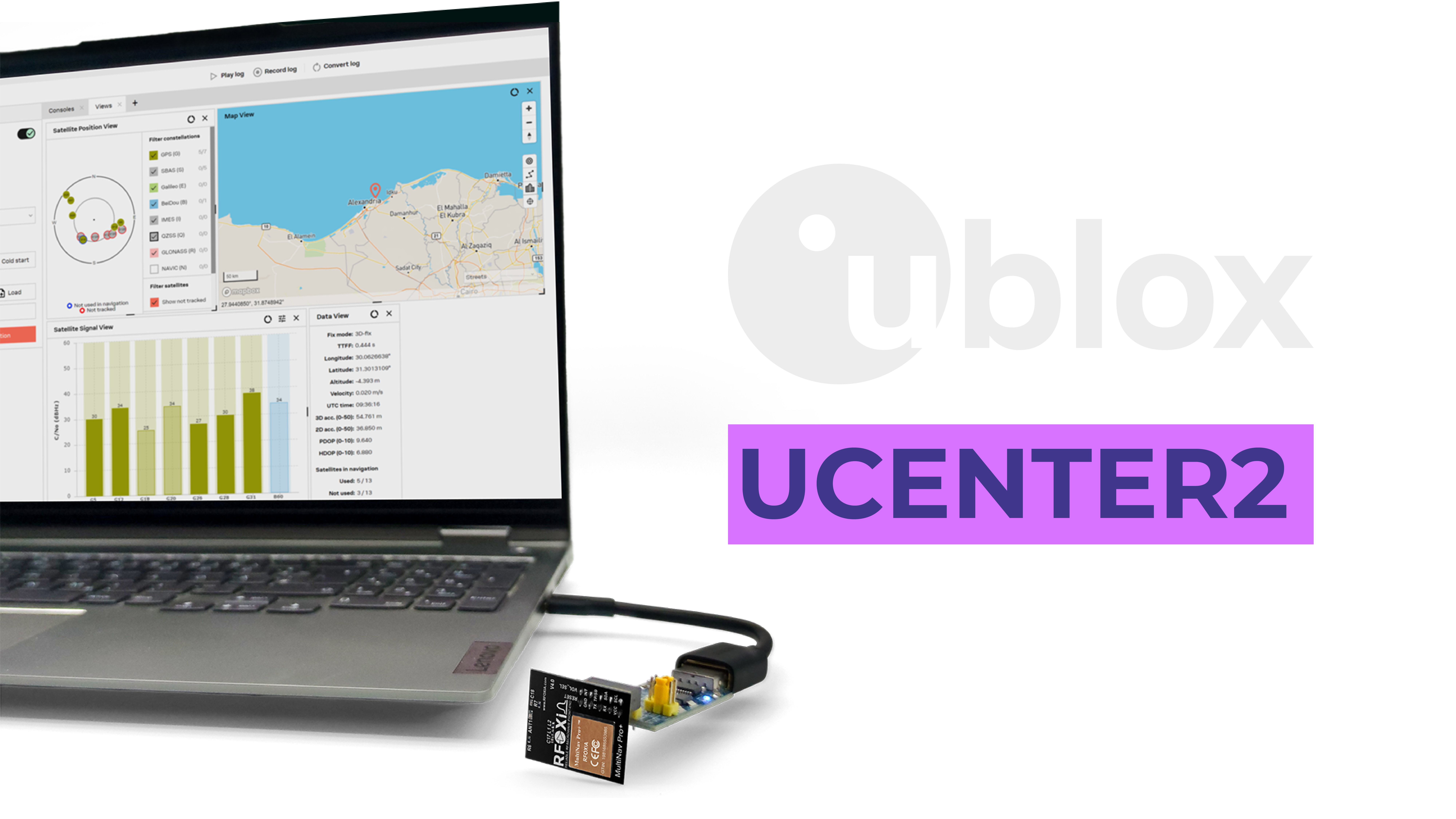
u-Center lets you:
- Visualize satellite signal strength and sky position for all four constellations
- Confirm fix quality and HDOP in real time
- Log position data to file for post-analysis
- Configure the module's output rate, enabled constellations, and NMEA sentence selection
- Evaluate position drift over time when stationary — critical for understanding your real-world accuracy floor
For geofencing validation, a useful pre-deployment test is to place the module at a known point and log 10 minutes of stationary position data. Plot the scatter of reported positions. The radius of that scatter cloud defines your effective position noise floor — and therefore the minimum viable geofence radius for that deployment environment.
With the MultiNav Pro+, typical stationary scatter in open-sky conditions stays within 1.5 meters. In partially obstructed environments (near buildings, tree canopy), expect 2-3 meters. Size your geofence boundaries accordingly.
Real-World GPS Geofencing Use Cases
Understanding the GPS geofencing module how to process is easier when grounded in real applications. Here are the most common deployment patterns across industries where the MultiNav Pro+ is actively used.

Drone return-to-home and no-fly enforcement Define a maximum operational radius from launch point. When the drone's GNSS position exceeds that radius, trigger an automatic return-to-home flight mode. At 18Hz and 1.5-meter accuracy, the trigger fires within 1-2 meters of the true boundary even at flight speeds above 15 m/s. This is also used for no-fly zone enforcement near airports or sensitive infrastructure.
Precision agriculture field zone management Define polygon geofences matching actual field boundaries. Sprayer systems activate only within the defined field polygon and cut off at boundary edges — preventing over-spray into adjacent land or buffer zones. Sub-2-meter accuracy means field boundary compliance is real, not approximate.
Fleet and asset tracking Vehicles trigger alerts when leaving approved service areas or entering restricted zones. With 18Hz updates, the position log captures every turn and movement detail rather than interpolating between sparse 1Hz samples.
Wearable safety systems Worker safety applications that alert supervisors when personnel enter hazardous zones or leave designated safe areas on industrial sites.
Smart city IoT deployments Environmental monitoring nodes that associate sensor data with specific zone IDs for district-level data aggregation. The RFOXiA Accurate GNSS Module is designed specifically for IoT deployments that require verified outdoor positioning — including RFOXiA's own data network, where GPS coordinates validate that sensor nodes are genuinely deployed outdoors.
Research and wildlife tracking Geofencing triggers event logging when tracked subjects enter or exit defined habitat zones, providing behavioral boundary data without requiring constant remote monitoring.
Integrating Geofencing With the Full RFOXiA Ecosystem
The MultiNav Pro+ is built to integrate with the broader RFOXiA hardware and software ecosystem, which creates capabilities beyond standalone GNSS geofencing.
When paired with the RFOXiA BLE Module (MultiNav Pro+ long-range BLE), your geofencing system gains wireless telemetry capability at ranges up to 20km for drone-to-ground links. Position data and geofence status can be transmitted in real time to a ground station or paired mobile device — without any cellular network or internet connectivity required.
The RFOXiA Connect app provides a live map interface that displays GPS position in real time, making it straightforward to monitor geofence status visually during field operations. Control commands can be triggered from the app when geofence events fire.
For data network applications, the GPS coordinates from the MultiNav Pro+ serve the critical function of validating that sensor nodes are genuinely deployed outdoors at their claimed locations — forming the verification backbone of RFOXiA's environmental data monetization network.
If you are building a complete wireless geofencing and telemetry system, the RFOXiA Accurate GNSS Module paired with the Developer Bundle gives you every hardware component in one integrated kit: GNSS, long-range wireless, environmental sensors, and professional power management.
Common GPS Geofencing Implementation Mistakes and How to Avoid Them
After covering the GPS geofencing module how to implementation path, here are the mistakes that consistently cause problems in real deployments:
Setting geofence radius smaller than your GNSS accuracy A 1-meter geofence radius on a module with 5-meter accuracy will trigger constantly from position noise. Always set minimum radius at least 2x your module's CEP specification. With the MultiNav Pro+ at 1.5m, a 3-meter minimum radius is a reasonable floor in open sky.
Running geofence checks on unvalidated fixes Always check fix quality, HDOP, and satellite count before running boundary logic. A fix with HDOP above 5.0 is too noisy for tight geofencing.
Ignoring fix rate requirements for moving platforms A 1Hz module on a fast drone means 10+ meters of travel between position updates. Match your fix rate to your platform speed and your required boundary precision.
Not accounting for coordinate system precision in storage Store latitude and longitude as double-precision floating point (float64). Single-precision float32 has insufficient precision at the 7th decimal place for sub-meter positioning — you will introduce rounding errors larger than your GNSS accuracy.
Hardcoding geofence coordinates in firmware For any production system, geofence definitions should be configurable at runtime — stored in non-volatile memory or received over wireless link. Hardcoded boundaries require a firmware flash to change, which is not practical in field-deployed systems.
Specifications Summary: MultiNav Pro+ GNSS Module
| Specification | Value |
|---|---|
| Accuracy | 1.5 meters CEP |
| Fix Rate | 18Hz |
| First Fix | 1 second |
| Constellations | GPS + GLONASS + Galileo + BeiDou (concurrent) |
| GNSS Chip | u-blox MIA-M10Q |
| Interface | UART (TX/RX) and I2C (SCL/SDA) |
| Operating Voltage | 1.8V / 3.3V |
| Current Draw | 25-30mA |
| Dimensions | 26mm x 22mm |
| Antenna | Integrated chip antenna |
| Software | Open-source C library, Arduino IDE compatible |
| Certification | FCC certified |
| Price | $49 |
Getting Started
If you are ready to move from reading to building, the MultiNav Pro+ is available now with inventory in stock. The module ships with the open-source driver library and a quick start guide. FCC certification means it is ready for US commercial and research deployment without additional regulatory work on your end.
For developers who want to integrate geofencing into a complete wireless system — including long-range telemetry, environmental sensing, and professional power management — the RFOXiA Developer Bundle combines every module in one kit at a price no modular ecosystem at this specification level can match.
Visit the RFOXiA Accurate GNSS Module product page for full documentation, library downloads, and to order.
Conclusion
The GPS geofencing module how to question always starts in the same place: what accuracy and update rate does your application actually require, and does your hardware deliver it?
Geofencing is not a software problem — it is a hardware-software system problem. The firmware logic is straightforward once you understand the coordinate math and the filtering requirements. The hard part is having position data accurate and fast enough to make your boundaries meaningful.
The MultiNav Pro+ from RFOXiA — 1.5-meter accuracy, 18Hz fix rate, concurrent four-constellation reception, 26mm x 22mm form factor, 25-30mA power draw — was built specifically for professional geofencing and location-aware applications where commodity modules fall short and industrial systems cost 10x too much.
Build something precise. Build something that works in the field, not just on the bench. And build it on GNSS hardware that gives you the accuracy your geofence boundaries deserve.
Written by: Moamen Mohamed LinkedIn