
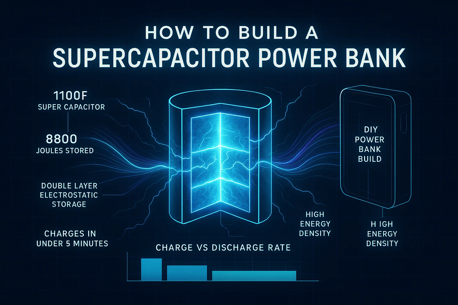
How to Build Supercapacitor Power Bank for Your Wireless Projects
RFOXiA SuperCapacitor Battery and Programmer Kit
The Complete Guide to Supercapacitor Power Banks — And Why Builders Are Switching From Lithium
Keyword: how to build supercapacitor power bank — Target density maintained throughout this guide.
If you have ever deployed a wireless sensor node in the field, piloted a drone to the edge of radio range, or left a long-range BLE module running overnight in a remote enclosure, you already know the enemy: battery downtime. You know the moment the voltage sag starts throwing off your readings, or the lithium cell refuses to charge in cold weather, or the balancing circuit inside a LiPo pack adds three hours to your recharge window.
Supercapacitors — sometimes called ultracapacitors or electric double-layer capacitors (EDLCs) — are a fundamentally different approach to energy storage that solves these problems at the physics level. This guide explains how to build a supercapacitor power bank, walks through the core engineering decisions you need to make, and then shows you what a production-ready implementation looks like in a real hardware product built for wireless developers.
By the end, you will understand whether a supercapacitor power bank is right for your project, how to design one from scratch if you want to, and where to get one that already works — tested, certified, and ready to ship.
What Is a Supercapacitor and Why Does It Matter?
A supercapacitor stores energy electrostatically — in an electric field — rather than chemically the way a lithium battery does. This has several important engineering consequences:
- Charge and discharge cycles are virtually unlimited. Lithium cells degrade measurably after 500–1,000 cycles. Supercapacitors are typically rated for 500,000 to 1,000,000 cycles.
- Charge rate is limited by your charging circuit, not by the cell chemistry. A lithium cell must be charged slowly to avoid thermal runaway and chemical damage. A supercapacitor accepts charge as fast as you can deliver current safely through your wiring.
- Discharge is smooth and voltage is predictable. Supercapacitors discharge in a linear voltage curve. This makes power regulation easier for downstream electronics.
- Temperature performance is excellent. Most supercapacitors operate from -40°C to +70°C without significant derating. Lithium cells lose substantial capacity below 0°C.
The tradeoff is energy density. Supercapacitors store far less energy per kilogram or per liter than lithium cells. For applications requiring multi-day runtime from a pocket-sized device, lithium still wins. But for applications requiring rapid recharge, high cycle life, field reliability, or wide temperature operation — supercapacitors are the correct engineering choice.
How to Build Supercapacitor Power Bank: Core Design Steps
If you are building your own supercapacitor power bank from components, here is the engineering path you need to follow.
Step 1 — Define Your Energy Requirements
Start with the load. What is the average current draw of your device in milliamps? What is the voltage it requires? How many hours of runtime do you need?
Energy in joules = Voltage (V) × Current (A) × Time (seconds)
For example: a wireless sensor node drawing 50mA at 3.3V for 8 hours requires: 3.3V × 0.05A × 28,800 seconds = 4,752 joules
Now account for efficiency losses in your voltage regulator (typically 85–92% for a good switching regulator) and for the fact that you cannot extract 100% of stored energy from a supercapacitor — the usable window is typically from maximum rated voltage down to half that voltage, which gives you 75% of stored energy.
So your required stored energy is approximately: 4,752 ÷ 0.88 ÷ 0.75 ≈ 7,200 joules
Step 2 — Select Your Supercapacitor Bank
Energy stored in a capacitor = ½ × C × V²
If you are using 2.7V cells in a series stack of two (giving 5.4V working voltage, which you regulate down), and you need 7,200 joules: 7,200 = ½ × C × 5.4² C = 7,200 ÷ (0.5 × 29.16) ≈ 494 farads
You would round up to a readily available capacitance value — for example, a pair of 600F 2.7V cells in series giving a 300F, 5.4V bank storing approximately 4,374 joules, or a higher-capacitance configuration depending on your runtime target.
Commonly available EDLC cells come in 100F, 350F, 500F, 650F, and 1200F ratings from manufacturers like Maxwell (now Vishay), Eaton, Nichicon, and Panasonic.
Step 3 — Design the Cell Balancing Circuit
When you place supercapacitor cells in series to reach higher voltages, you must actively balance them. Unlike lithium packs where balancing is optional in some configurations, supercapacitors have slightly different self-discharge rates between cells. Without balancing, one cell will be overcharged while another is undercharged, reducing both capacity and cell life.
Passive balancing uses a resistor in parallel with each cell. Simple, low cost, but wastes energy continuously. Use a resistor value low enough to overcome the maximum leakage current differential between cells — typically a few ohms to tens of ohms depending on cell size.
Active balancing uses a switched-mode circuit to transfer charge between cells. More efficient, more complex, appropriate for larger banks or applications where standby self-discharge matters.
Step 4 — Design the Charging Circuit
Supercapacitors should be charged with a constant-current source, transitioning to a constant-voltage hold at the maximum rated voltage. This is actually simpler than lithium charging — there is no CC/CV chemistry to manage, no temperature sensing required for safety, and no trickle charge phase.
For a bank charged from a 12V adapter to a 5.4V supercapacitor stack, a synchronous buck converter IC like the LTC3780 or MP2307 configured for constant current limiting works well. Size the current limit based on your charge time target and thermal budget of your cabling and PCB traces.
Charge time = (C × ΔV) ÷ I_charge For 300F charged from 0V to 5.4V at 10A: (300 × 5.4) ÷ 10 = 162 seconds ≈ 2.7 minutes
Step 5 — Design the Output Regulation Stage
Your load likely requires a regulated voltage — 3.3V for most microcontrollers and BLE modules, 5V for some peripherals. Use a synchronous step-down converter between the supercapacitor bank and your load. A buck converter with a wide input voltage range (to accommodate the supercapacitor voltage dropping from full to half) and low quiescent current (to minimize standby drain) is ideal.
Good options include the TPS62840 for ultra-low quiescent current applications, or the TPS563201 for higher current loads.
Step 6 — Mechanical Integration and Thermal Considerations
Large supercapacitor cells are cylindrical and physically substantial. An 1100F cell at 2.7V is roughly the size of a large D-cell battery. Plan your enclosure accordingly. Supercapacitors tolerate vibration and mechanical stress far better than lithium cells — no liquid electrolyte to leak, no dendrite formation, no thermal runaway risk. This makes them genuinely suited to drone and field deployment applications.
Heat dissipation in the charging circuit is the main thermal challenge. At 10A charging current through a buck converter with 88% efficiency, your switching losses are approximately 12W × (1-0.88) = roughly 1.4W of heat to manage. Size your copper pours and add thermal vias accordingly.
The Engineering Shortcut: A Production-Ready Supercapacitor Power Bank Built for Wireless Developers
Designing your own supercapacitor power bank is a rewarding engineering exercise — but it is also a multi-week PCB design and testing project before you have solved the actual problem you set out to solve: powering your wireless development.
This is exactly why RFOXiA built the MultiNav Pro+ Power/Program Kit.
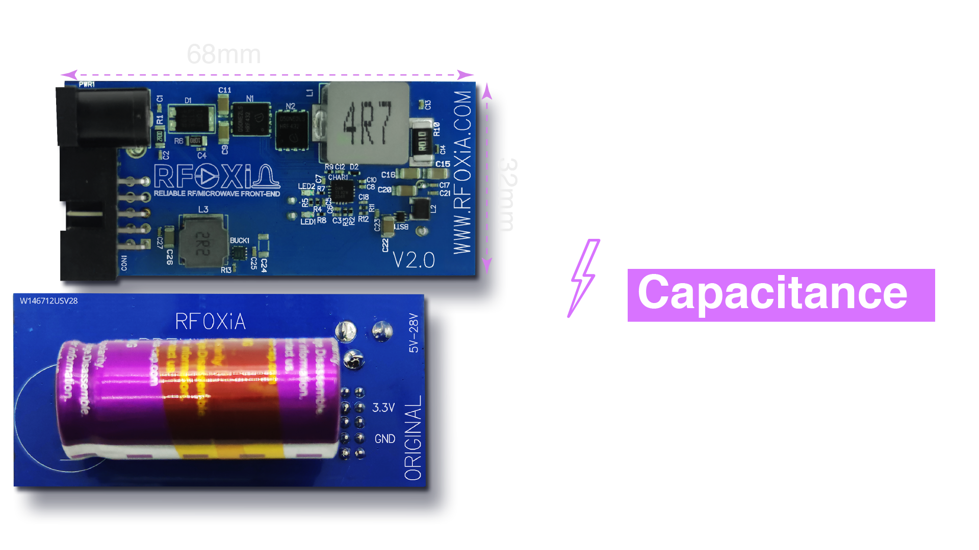
The Power/Program Kit is built around an 1100F supercapacitor system storing 8,800 joules — enough to power the complete MultiNav Pro+ module stack (BLE module, GNSS module, and sensors module simultaneously) for a full working day. It charges from a 12V 5A adapter in under 5 minutes. Not under an hour. Not 30 minutes. Under 5 minutes.
This is what knowing how to build a supercapacitor power bank correctly actually looks like in practice.
Every component decision in this kit was made by a hardware engineer who has done the math, sourced the cells, designed the balancing and regulation circuits, and tested the result in real field conditions. The result is FCC certified, ships with all necessary cables, and integrates directly with the MultiNav Pro+ ecosystem without any additional power engineering on your part.
Inside the MultiNav Pro+ Power/Program Kit
The Supercapacitor Bank
At the heart of the kit is the 1100F supercapacitor bank. To put that in context: 1100 farads at 4V stores 8,800 joules of usable energy. For a wireless sensor node, GNSS receiver, and long-range BLE module running simultaneously, that is a full day of continuous operation from a 5-minute charge.
The bank is engineered with proper cell balancing integrated into the board design. You do not need to think about cell matching, balancing resistors, or voltage drift between cells. It is handled.
The High-Power Charging Adapter
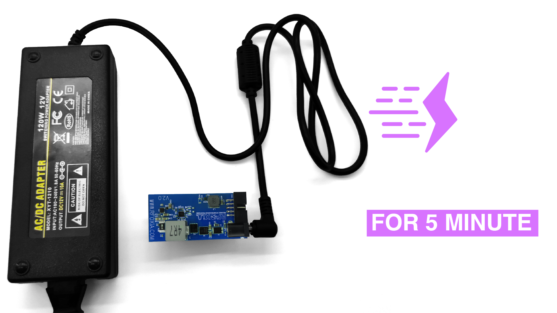
The included 12V 5A adapter delivers charge current to the supercapacitor bank at 4V and 10A — the charging circuit steps down voltage and boosts current from the adapter to the bank efficiently. This is why the charge time is so short. You are not limited by slow CC/CV lithium chemistry. The supercapacitor accepts charge as fast as your charging circuit can deliver it, and this circuit is designed to deliver it quickly.
In a field deployment scenario, this means a dead kit becomes a fully charged kit in the time it takes to drink a coffee. This is not a specification that lithium battery systems can match at any price point.
Full-Day Module Power
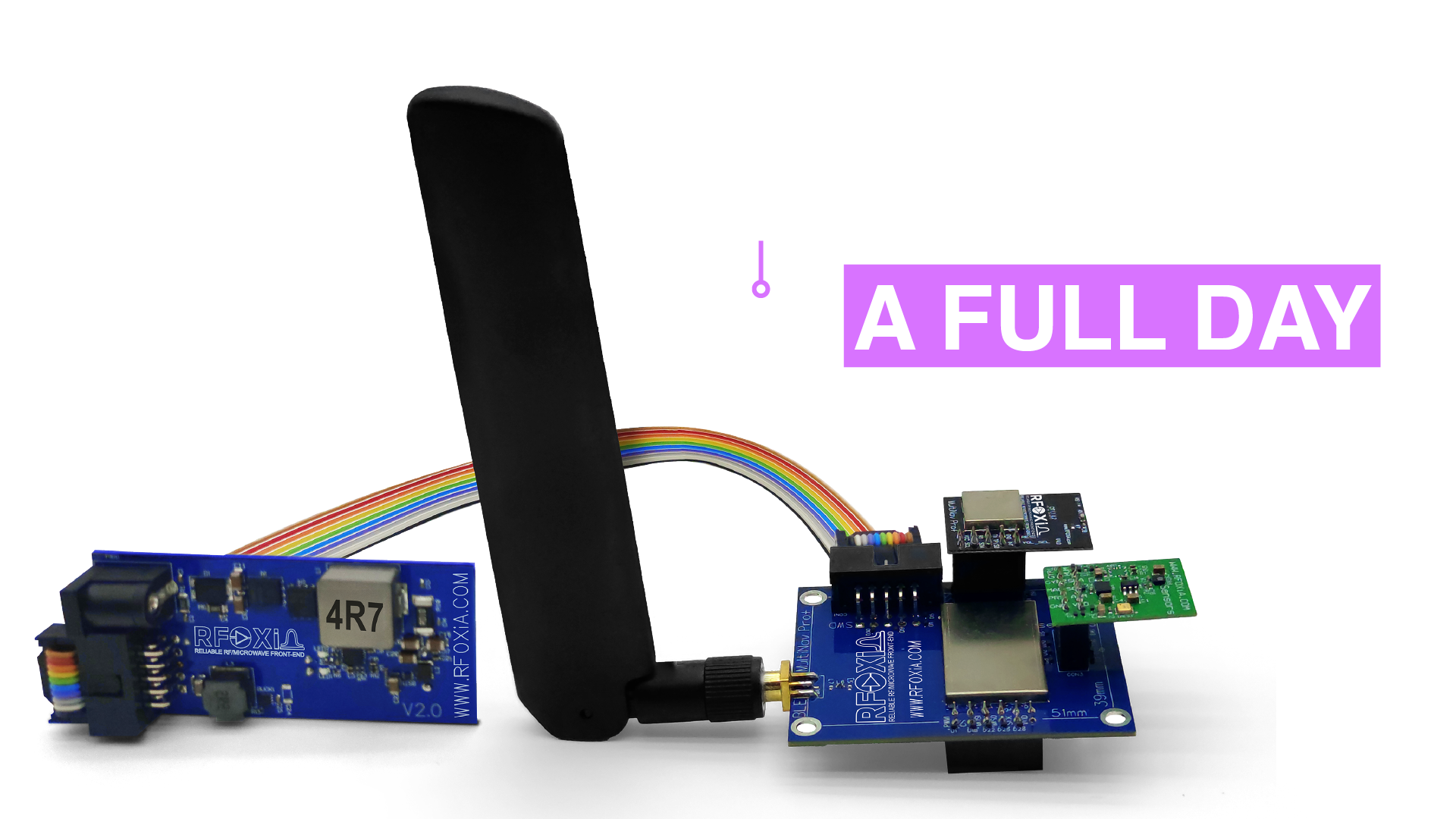
The power output stage is designed to run the complete MultiNav Pro+ stack — not just the BLE module alone, but the BLE module, GNSS module, and all seven sensors in the Sensors Module simultaneously. Running all four modules together for an entire working day from a single 5-minute charge is the practical specification that matters for real deployment.
This is the specification that makes the kit viable for field researchers, drone operators, and IoT deployments where you need your hardware to work all day without intervention.
The Integrated STLink Programmer
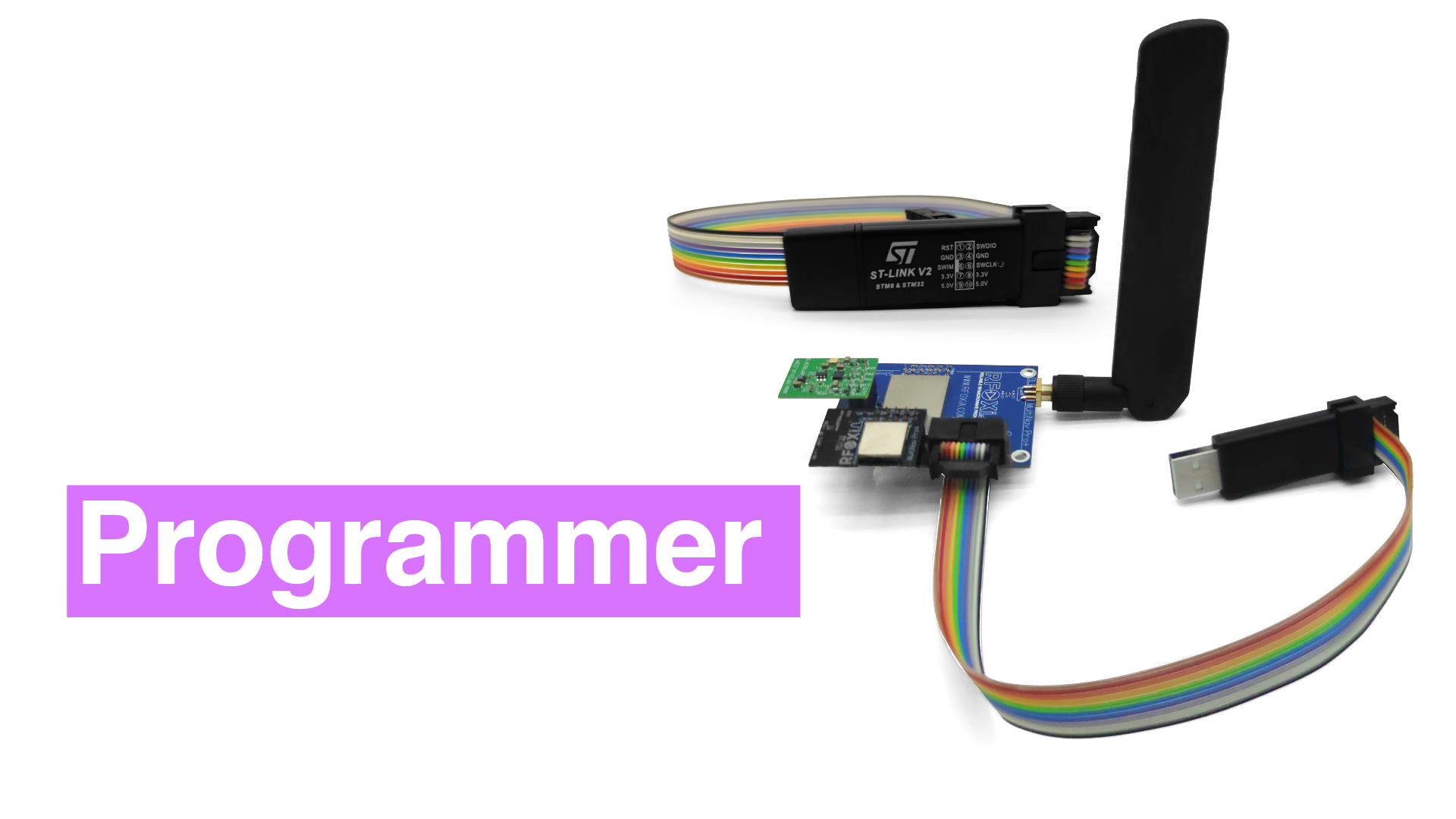
This is where the Power/Program Kit becomes something beyond a battery solution. Included in the kit is a fully integrated STLink programmer interface designed specifically for the MultiNav Pro+ BLE Module.
The MultiNav Pro+ BLE Module runs on an STM32WB07 microcontroller. Flashing custom firmware — whether you wrote it yourself, generated it with the RFOXiA AI Firmware Builder, or pulled it from the RFOXiA GitHub repository — requires an STLink interface. This kit provides that interface natively, integrated into the same board as your power supply.
That means your programming environment and your power supply are the same device. You power your module and flash your firmware from the same connection, with the same cable. No external programmer dongle. No jumper wire gymnastics. No USB-to-SWD adapters sourced separately.
For developers who are actively iterating on firmware — which is everyone who is building something real — this integration matters enormously. The RFOXiA SuperCapacitor Battery and Programmer Kit removes two friction points from your development loop simultaneously.
Complete Connectivity Hardware
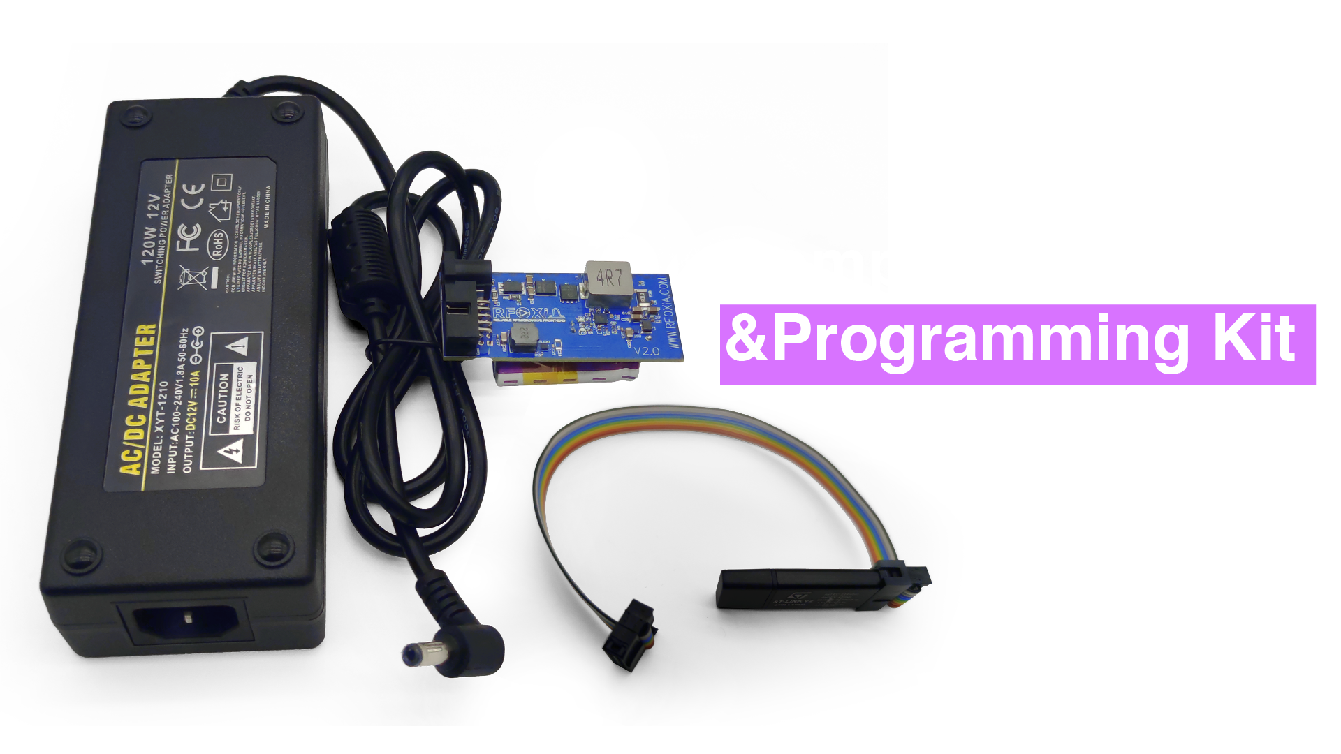
Every cable you need is included. Flat ribbon cables connect the BLE module to the power module and the STLink programmer to the BLE module. There is no hunting for the right connector pitch or ordering separate cables. The kit arrives complete and functional out of the box.
Who Should Use a Supercapacitor Power Bank Like This?
Understanding how to build a supercapacitor power bank helps you recognize when the design philosophy is the right match for your application. Here are the use cases where supercapacitor-based power systems genuinely outperform lithium alternatives:
Drone developers and FPV builders — Drones operate in vibration-heavy, temperature-variable environments. Supercapacitors tolerate both far better than lithium cells. When your drone lands and you want to pull telemetry and reflash firmware before the next flight, a 5-minute charge cycle matches your workflow. A 2-hour lithium charge cycle does not.
Field researchers and environmental scientists — Deploying wireless sensor nodes in remote locations means carrying charging infrastructure. A 12V 5A adapter that fully charges your node in 5 minutes from a vehicle outlet or portable generator is operationally very different from carrying multiple lithium battery packs for battery swapping.
IoT developers running data network nodes — The RFOXiA data network rewards continuous uptime. A power system that charges in 5 minutes eliminates the gap between charging sessions, maximizing the time your sensors are streaming verified data and earning daily rewards.
Robotics engineers — Wheeled and legged robots in laboratory environments benefit from rapid charge cycles between test runs. Waiting 90 minutes for a lithium pack to charge between 20-minute test runs is inefficient. A 5-minute supercapacitor recharge fits the development loop.
Embedded systems developers actively iterating on firmware — Every firmware development session involves repeated flash-test-debug cycles. Having your power supply and programmer integrated into the same device, always charged and always ready, removes friction from the development loop.
Supercapacitor vs Lithium Battery: The Honest Comparison
| Property | Supercapacitor Power Bank | Lithium Battery Pack |
|---|---|---|
| Charge time | 3–5 minutes | 60–180 minutes |
| Cycle life | 500,000+ cycles | 500–1,000 cycles |
| Low-temperature performance | Excellent (-40°C) | Degraded (significant below 0°C) |
| Energy density | Lower | Higher |
| Thermal runaway risk | None | Present (managed by BMS) |
| Self-discharge rate | Higher (weeks to months) | Lower (months) |
| Best application | High-cycle, rapid-recharge, field deployment | Long-duration, infrequent recharge |
For the specific use case of powering a wireless development stack through an active development and deployment cycle, the supercapacitor profile wins on the metrics that matter most: charge time, cycle life, and field reliability.
The RFOXiA Ecosystem Context
The Power/Program Kit is designed as part of the complete RFOXiA wireless development ecosystem. When combined with the MultiNav Pro+ BLE Module (5km ground-to-ground, 20km man-to-drone range), the GNSS Module (18Hz fix rate, 1.5m accuracy), and the Sensors Module (seven sensors including air quality, accelerometer, and magnetometer), the Power/Program Kit becomes the infrastructure layer that keeps the entire stack running.
The Developer Bundle — which includes all four modules together — is the fastest path to a complete wireless development platform. The Power/Program Kit is included in the bundle, meaning when you learn how to build a supercapacitor power bank and decide you want a production-ready version, you can get it as part of a complete ecosystem rather than as a standalone component.
All four modules in the ecosystem are FCC certified. This is not a caveat or a qualifier — it means you can deploy these devices in the United States commercially without additional regulatory work, and it means distributors will stock them.
Specifications Summary
Supercapacitor Bank
- Capacitance: 1100F
- Stored energy: 8,800 joules
- Charge time: under 5 minutes
- Runtime: full working day powering complete MultiNav Pro+ module stack
Charging Adapter
- Input: 12V 5A (included)
- Charging current to bank: 4V at 10A
Programmer Interface
- Type: STLink
- Compatible: MultiNav Pro+ BLE Module (STM32WB07)
- Supports: firmware flashing and debug
Included Accessories
- 12V 5A charging adapter
- Flat ribbon cable: power module to BLE module
- Flat ribbon cable: programmer to BLE module
Certification
- FCC certified
Price
- $119
Conclusion: Build It or Buy It — But Use Supercapacitors
Now you know how to build a supercapacitor power bank. You understand the energy calculations, the cell selection, the balancing circuit design, the charging architecture, and the output regulation requirements. If you have the time and the PCB design skills, building your own is a genuinely rewarding project and gives you exactly the energy capacity and form factor you need for your specific application.
If your goal is to build something wireless — a long-range drone control system, a field sensor network, a robotics platform — rather than to build a power supply, the RFOXiA SuperCapacitor Battery and Programmer Kit gives you a production-quality supercapacitor power bank with an integrated firmware programmer, all the cabling you need, and FCC certification, for $119.
That is how you build a supercapacitor power bank: understand the engineering, make the right design choices, and either implement it yourself or pick up the implementation that already works and get back to building what you actually set out to build.
Ready to power your wireless projects without the downtime? Explore the complete MultiNav Pro+ ecosystem at rfoxia.com.
Written by: Moamen Mohamed LinkedIn