
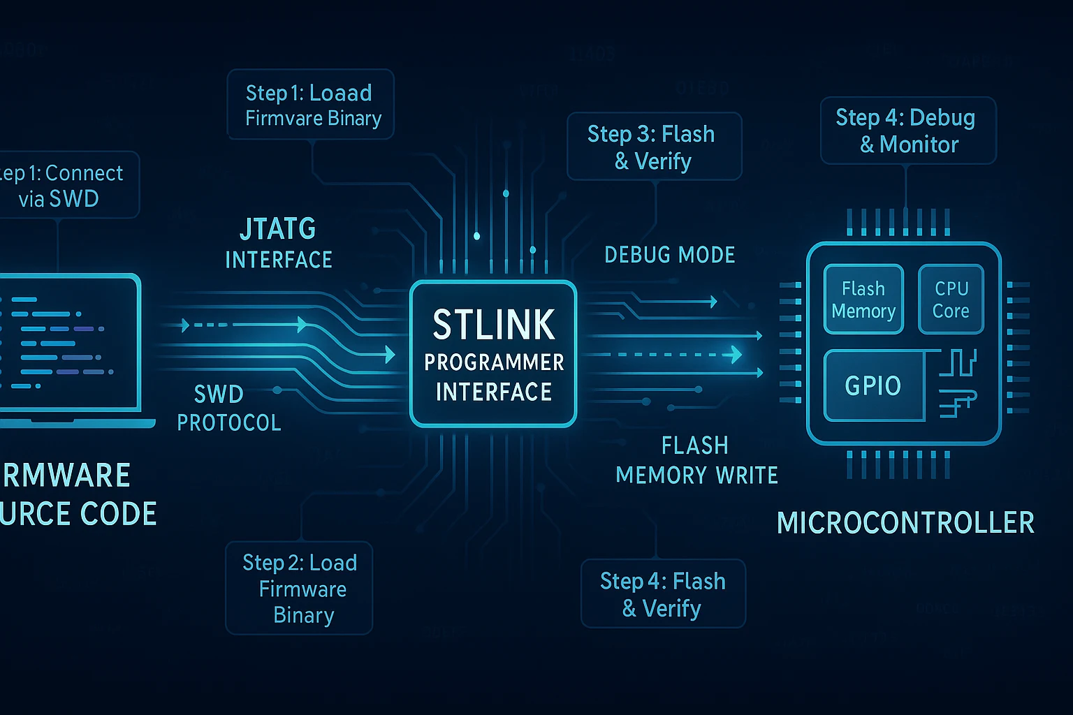
How to Use STLink Programmer with the MultiNav Pro+ Power/Program Kit
RFOXiA SuperCapacitor Battery and Programmer Kit
How to Use STLink Programmer to Flash, Debug, and Power Your MultiNav Pro+ BLE Module Like a Professional
If you have ever spent hours wrestling with unreliable USB-to-serial adapters, voltage mismatches, or fragile power setups just to flash firmware onto a wireless module, you already know the frustration. Development boards are only as capable as the toolchain behind them, and a weak toolchain kills momentum faster than any bug in your code.
The RFOXiA SuperCapacitor Battery and Programmer Kit was built to eliminate exactly that problem. This guide walks you through how to use STLink programmer hardware alongside the MultiNav Pro+ Power/Program Kit's integrated supercapacitor power system — giving you a complete, professional-grade setup that charges in under five minutes and keeps your module running for a full working day.
Whether you are building a long-range drone telemetry link, deploying a remote IoT sensor node, or developing custom firmware for the MultiNav Pro+ BLE Module, this is the setup guide you need.
What Is the STLink Programmer and Why Does It Matter?
The STLink is a debug and programming interface developed by STMicroelectronics. It connects your host computer to an STM32 microcontroller using the SWD (Serial Wire Debug) protocol — a two-wire interface that gives you full control over the target chip: flashing firmware, setting breakpoints, reading registers, and monitoring live memory values.
The MultiNav Pro+ BLE Module is built around the STM32WB07 — a dual-core wireless SoC that handles both the application layer and the Bluetooth Low Energy radio stack simultaneously. To program this chip efficiently, you need an SWD-compatible programmer. The STLink is the definitive tool for that job.
Using an STLink programmer instead of a bootloader-based USB approach gives you several critical advantages:
- Full chip access: You can erase, write, and verify all flash regions including the wireless stack firmware
- Live debugging: Set breakpoints and step through code execution in real time using an IDE like STM32CubeIDE or VS Code with Cortex-Debug
- Reliable flashing: SWD is far more robust than UART bootloader methods for production and field updates
- No bootloader dependency: You are not limited by what the bootloader exposes — the programmer has direct memory access
The MultiNav Pro+ Power/Program Kit includes an integrated STLink programmer interface specifically matched to the MultiNav Pro+ BLE Module's pinout, so no jumper wire guessing, no voltage level shifting, and no adapter hunting.
What Is Inside the MultiNav Pro+ Power/Program Kit?
Before diving into the step-by-step programming guide, it helps to understand what you are working with. The kit is a purpose-built companion for the entire MultiNav Pro+ module ecosystem.
Supercapacitor Battery System
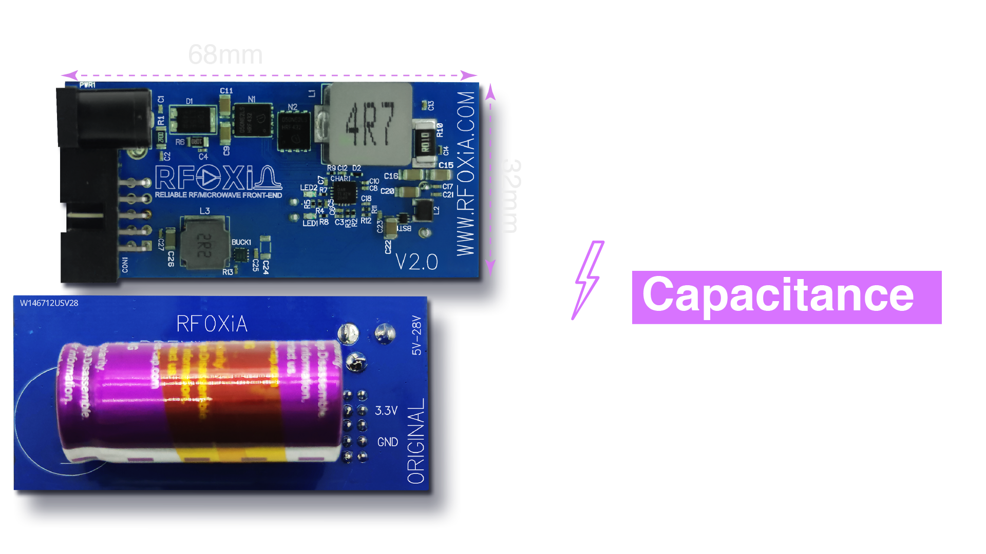
The power heart of this kit is a 1100F supercapacitor system storing 8800 Joules of energy. This is not a lithium battery. Supercapacitors charge and discharge through a fundamentally different electrochemical mechanism — one that allows extraordinarily fast charge times and virtually unlimited charge cycles with no degradation over time.
The practical result: your power module charges fully in under five minutes and can run your complete MultiNav Pro+ module stack — BLE Module, GNSS Module, and Sensors Module simultaneously — for a full 24-hour working day. For field development and deployment work, this is a game changer. No more waiting hours for a lithium pack to top off. No more battery swaps mid-session.
High-Power Charging Adapter
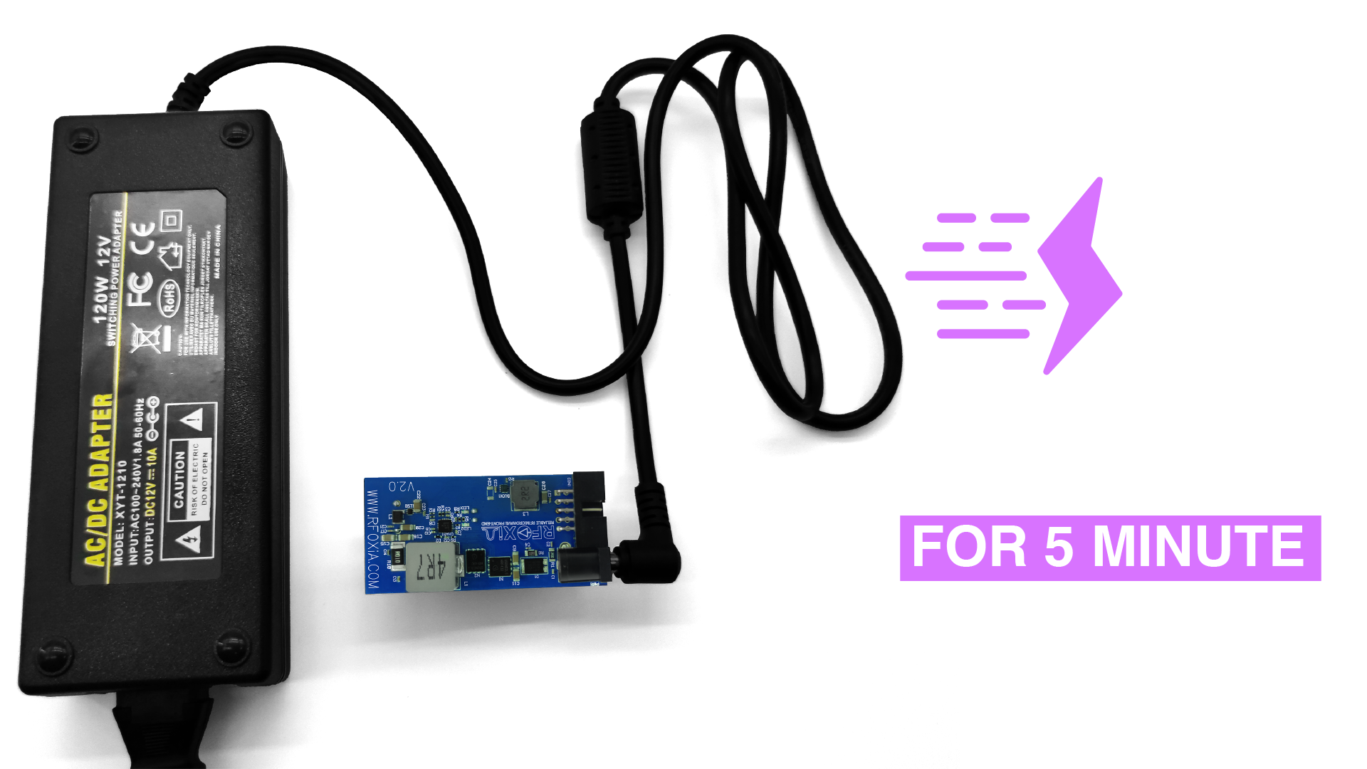
To charge the supercapacitor system at its rated speed, the kit includes a dedicated 12V 5A high-power adapter. The charging circuit steps this down and delivers current to the supercapacitors at 4V 10A — the optimal charge profile for the supercapacitor stack. This is not an ordinary wall adapter. The combination of input and output specs is engineered specifically to fill 1100F in under five minutes without thermal stress on the capacitor cells.
Plug in, wait five minutes, and you have a full day of power. That is the intended workflow.
Full-Day Module Power Delivery
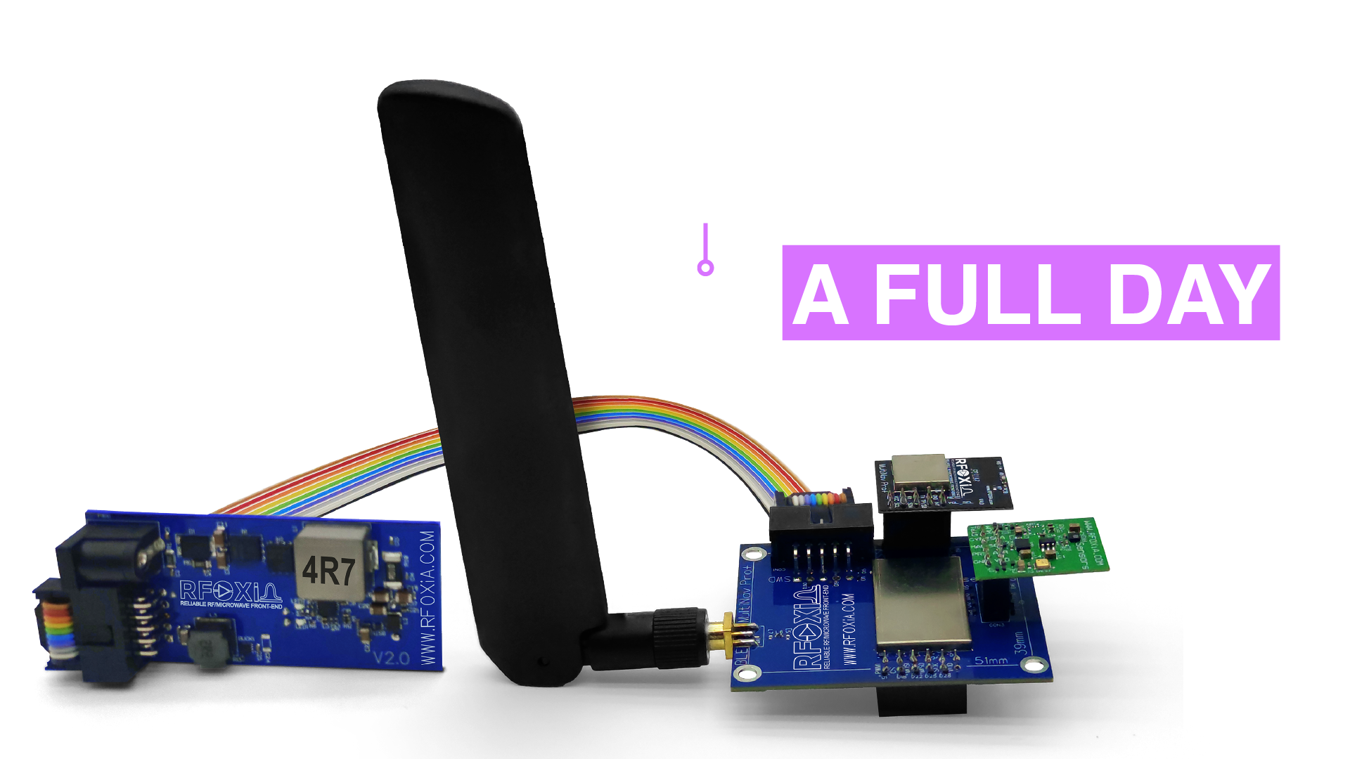
The Power/Program Kit is not sized just for the BLE Module. It is designed to power the entire MultiNav Pro+ ecosystem simultaneously. Running the BLE Module, GNSS Module, and Sensors Module together draws meaningful current, especially when the RF amplifiers are active and the GNSS receiver is acquiring satellites. The 8800 Joule capacity handles this full load comfortably for 24 hours of continuous operation.
For field deployments — whether that means a remote sensor node, a drone-based telemetry link, or a search-and-rescue communication relay — you can leave a fully charged kit in the field and it will still be running the next morning.
Integrated STLink Programmer Interface
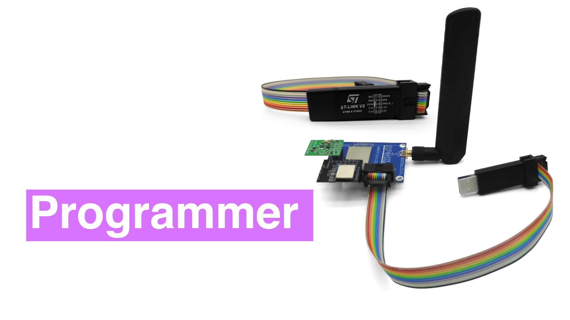
The integrated STLink programmer interface is what makes this kit genuinely special for developers. Rather than requiring an external programmer, a separate power supply, and a custom cable harness, everything lives in one board. The STLink interface connects directly to the MultiNav Pro+ BLE Module's SWD pins through the included flat ribbon cables, giving you a clean, reliable programming and debugging connection every time.
Complete Connectivity Kit
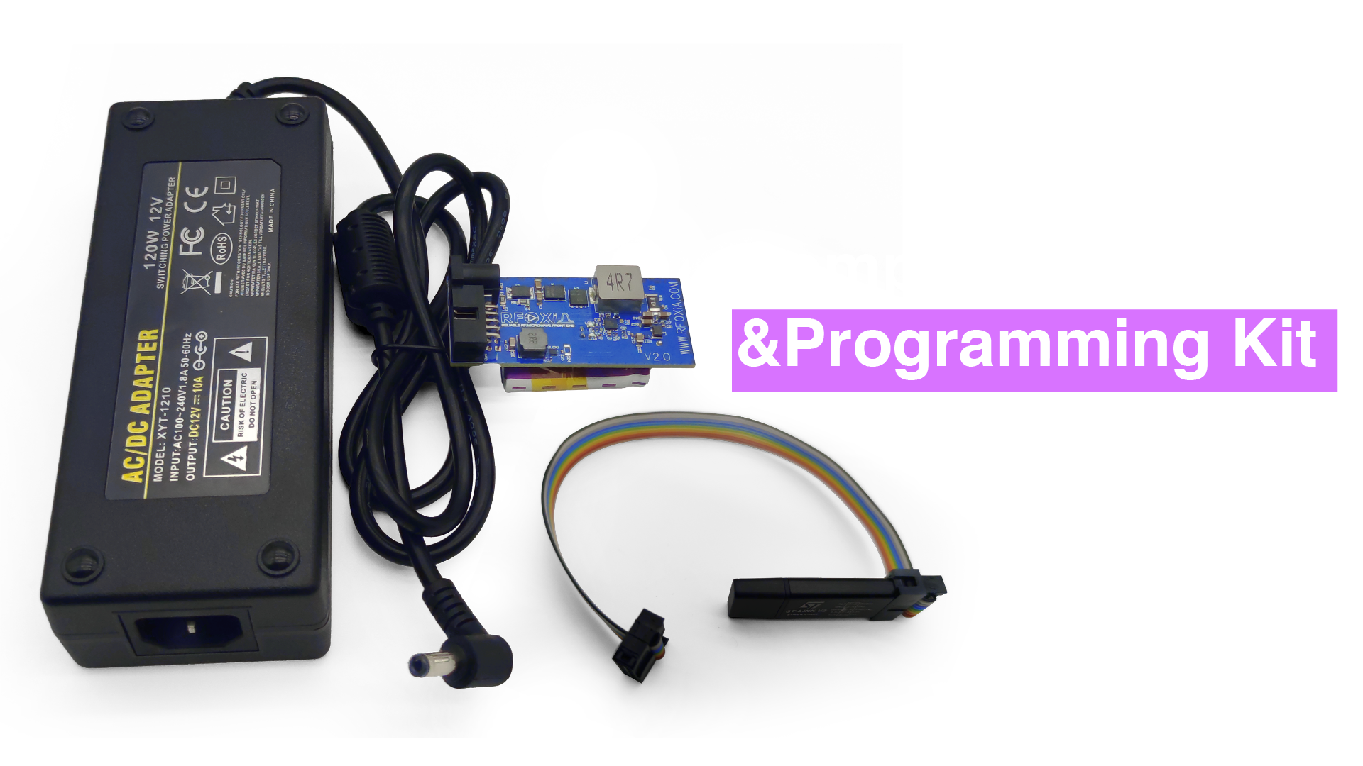
The kit ships with all cables required for immediate use. Flat ribbon cables connect the BLE Module to the power board and connect the STLink programmer interface to the BLE Module's programming header. No hunting for obscure cables, no breadboard wiring, no chance of a loose jumper causing a failed flash. Everything plugs in and works.
How to Use STLink Programmer: Complete Step-by-Step Guide
This section covers the complete workflow from unboxing to successfully flashing firmware onto your MultiNav Pro+ BLE Module.
Step 1: Install the Required Software Tools
Before connecting any hardware, set up your programming toolchain on your host computer.
STM32CubeProgrammer is the primary tool for flashing firmware using an STLink. Download it from the STMicroelectronics website. It is available for Windows, macOS, and Linux and requires no license purchase.
If you plan to do live debugging in addition to flashing, install STM32CubeIDE, which bundles the GCC ARM toolchain, OpenOCD, and the STLink GDB server into a single IDE package. Alternatively, if you prefer VS Code, install the Cortex-Debug extension and configure it with the STLink GDB server.
Step 2: Connect the Power/Program Kit to Your Module
Lay out your MultiNav Pro+ Power/Program Kit and your MultiNav Pro+ BLE Module on a clean, static-safe surface.
- Attach the flat ribbon power cable from the Power/Program Kit's power output connector to the BLE Module's power input header. The connector is keyed — it only seats in the correct orientation.
- Attach the flat ribbon programmer cable from the integrated STLink interface connector on the Power/Program Kit to the SWD programming header on the BLE Module. Again, the cable is keyed.
- Connect the USB cable from the Power/Program Kit's STLink USB port to your host computer. The STLink programmer draws power from USB — no separate power required for the programmer itself.
Step 3: Charge the Supercapacitor System (If Needed)
If you are also running the module from the supercapacitor system during development (recommended for consistent voltage), connect the included 12V 5A adapter to the charging port on the Power/Program Kit. The charge indicator will confirm charging status. In under five minutes, the system is fully charged and ready to power your module for the rest of the day.
Step 4: Verify STLink Connection in STM32CubeProgrammer
Open STM32CubeProgrammer on your host computer.
- In the connection interface panel on the right side, select ST-LINK from the interface dropdown.
- Set the connection mode to SWD.
- Click Connect.
STM32CubeProgrammer will detect the STLink programmer and interrogate the target STM32WB07. If the connection is successful, you will see the device information panel populate with the chip's unique ID, flash size, and memory map. This confirms that your STLink connection to the MultiNav Pro+ BLE Module is working correctly.
If the connection fails, check:
- USB cable is seated at both ends
- Ribbon cables are fully inserted at both connectors
- The power module is providing power to the BLE Module (check the power LED on the BLE Module)
Step 5: Load Your Firmware Binary
In STM32CubeProgrammer, navigate to the Erasing and Programming section (the download icon in the left sidebar).
Click Browse and navigate to your compiled firmware binary. For MultiNav Pro+ projects, this will be a .hex or .bin file output from your build system. If you are using the RFOXiA AI Firmware Builder in the RFOXiA Club Dev Hub, the generated firmware project will compile to a standard .hex file using the STM32WB07 toolchain.
Set the start address to match your firmware's target region. For application code on the STM32WB07, this is typically 0x08000000. The .hex file format includes address information and sets this automatically.
Enable Verify programming — this option reads back the flashed memory and compares it against your binary to confirm the write was error-free.
Step 6: Flash and Verify
Click Start Programming. STM32CubeProgrammer will:
- Erase the target flash sectors
- Write your firmware binary
- Verify the written data against the source file
- Report success or flag any errors
The entire process for a typical MultiNav Pro+ firmware image takes under 30 seconds. When complete, click Disconnect in STM32CubeProgrammer and then power cycle the BLE Module using the power switch on the Power/Program Kit. Your new firmware will boot immediately.
Step 7: Live Debugging (Optional but Recommended)
Knowing how to use STLink programmer for flashing is only half of its capability. The debugger is where development velocity really accelerates.
In STM32CubeIDE, open your firmware project and create a new STM32 Cortex-M C/C++ Application debug configuration. Set the interface to SWD and the connection to your STLink. With the Power/Program Kit connected, click Debug.
The IDE will flash the latest build and halt execution at the entry point. From here you can:
- Step through code line by line
- Set breakpoints on specific functions
- Watch live variable values and peripheral register states
- Monitor RTOS task states if using FreeRTOS
- Profile timing-critical sections of your RF link code
For building long-range BLE applications on the STM32WB07, live debugging access to the radio stack's event queue and timing parameters is invaluable. It is the difference between guessing why your connection drops at 4km and knowing exactly which parameter to adjust.
Common Issues and How to Solve Them
STLink Not Detected by STM32CubeProgrammer
This usually means a driver issue on Windows. Install or reinstall the STLink USB driver using the STSW-LINK009 driver package from STMicroelectronics. On macOS and Linux, the STLink is typically detected automatically via libusb.
Target Not Found After STLink Connects
If the programmer connects but cannot find the target microcontroller, verify that the BLE Module is powered. The SWD interface requires the target chip to be running. Confirm the Power/Program Kit is providing voltage to the BLE Module and check the ribbon cable connection at both ends.
Verification Failed After Programming
Occasionally, a verification failure points to a flash protection state on the chip. In STM32CubeProgrammer, navigate to the Option Bytes section and check the read protection level. If it is set above level 0, you may need to perform a full chip erase before programming. Note that this erases all existing firmware.
Firmware Boots but Module Does Not Respond as Expected
If the flash succeeds but behavior is unexpected, connect the debug interface and step through initialization. The most common culprits are clock configuration mismatches or an incorrect RF stack initialization sequence. The RFOXiA GitHub repository at https://github.com/RFOXiA/MultiNav-Pro-Long-Range-BLE-Module-Firmware-STM32WB07 contains reference firmware and initialization examples.
Why the Power/Program Kit Changes Your Development Workflow
Most developers working with wireless modules build an ad hoc setup: bench power supply wired to the module, external STLink dongle velcroed somewhere, a tangle of jumper wires, and a USB hub holding it all together. This works, but it is fragile, time-consuming to set up, and completely impractical for field work.
The MultiNav Pro+ Power/Program Kit collapses this entire setup into a single, integrated board. Plug in two ribbon cables and a USB cable and you have professional-grade power management and a complete STLink programming interface ready to go. The five-minute supercapacitor charge cycle means you can charge the kit during a coffee break and have a full day of power on hand.
For anyone building production devices on the MultiNav Pro+ platform — whether that is a commercial drone, a distributed environmental sensor network, or a custom long-range communication device — this kit is the professional infrastructure layer your project needs.
If you are ready to stop fighting your toolchain and start building, the RFOXiA SuperCapacitor Battery and Programmer Kit is available now in the RFOXiA store.
Integrating with the RFOXiA Ecosystem
The Power/Program Kit does not exist in isolation. It is designed as part of the complete MultiNav Pro+ ecosystem alongside:
- MultiNav Pro+ BLE Module — 5km ground-to-ground, 20km man-to-drone, 50km drone-to-drone Bluetooth range
- GNSS Module — 1.5m accuracy, 18Hz fix rate for high-speed drone tracking
- Sensors Module — seven environmental sensors in one compact board
- RFOXiA Connect App — PS5-style drone and robot control with live GPS mapping, no internet required
- RFOXiA Club AI Firmware Builder — describe your application in plain language, receive production-ready firmware
The Developer Bundle combines all four hardware modules at a significant discount and pairs with the AI Firmware Builder so you can move from idea to functioning firmware in hours rather than weeks. Understanding how to use STLink programmer effectively means you can take that AI-generated firmware, flash it onto your hardware, and iterate in real time using live debugging — the complete professional development loop.
Technical Specifications Summary
| Feature | Specification |
|---|---|
| Supercapacitor Capacity | 1100F |
| Energy Storage | 8800 Joules |
| Full Charge Time | Under 5 minutes |
| Runtime (Full Module Stack) | 24 hours |
| Charging Input | 12V 5A |
| Charging Output to Supercapacitors | 4V 10A |
| Programmer Interface | STLink (SWD protocol) |
| Target MCU | STM32WB07 (MultiNav Pro+ BLE Module) |
| Cable Included | Flat ribbon cables for power and programmer |
| FCC Certified | Yes |
Final Thoughts
Knowing how to use STLink programmer properly is one of the most valuable skills in the embedded developer's toolkit. It gives you direct, reliable access to your microcontroller's memory and execution state — the foundation of professional firmware development. Combined with the MultiNav Pro+ Power/Program Kit's supercapacitor power system, you have a setup that is faster to deploy, more reliable in the field, and more capable at the bench than any ad hoc solution you could assemble from spare parts.
The five-minute charge cycle alone eliminates one of the most persistent friction points in embedded hardware development. Add integrated STLink access and a full connectivity kit, and this is simply the most efficient way to develop and deploy MultiNav Pro+ firmware.
Visit the RFOXiA SuperCapacitor Battery and Programmer Kit product page to get yours and complete your MultiNav Pro+ development stack.
Written by: Moamen Mohamed LinkedIn