
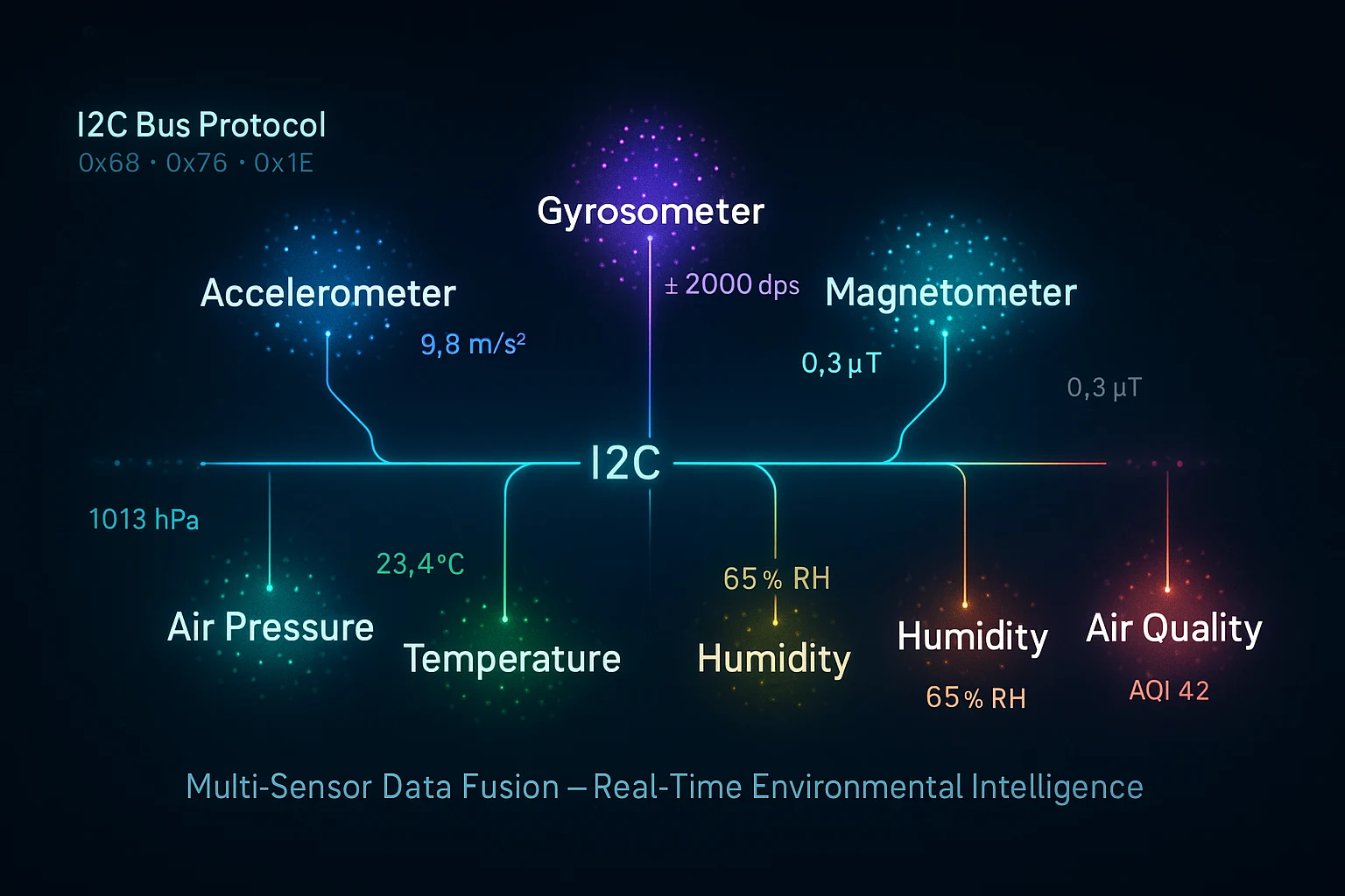
I2C Sensor Module Tutorial: How to Build Smarter IoT and Drone Projects with 7 Sensors on One Board
RFOXiA Integrated Sensors Module
The Definitive I2C Sensor Module Tutorial for Makers, Drone Builders, and IoT Engineers
If you've ever tried to wire five or six different sensor breakouts onto a single microcontroller — managing addresses, debugging collisions, untangling spaghetti wiring on a breadboard — you already know the pain. This I2C sensor module tutorial exists to solve exactly that problem.
We're going to walk through everything: what the I2C protocol is and why it matters, how multi-sensor modules eliminate the complexity of individual breakouts, how to wire, address, and read from multiple sensors sharing a single bus, and how to get real data flowing from a professional-grade all-in-one sensor board into your project.
The hardware we're using throughout this tutorial is the MultiNav Pro+™ Sensors Module from RFOXiA — a 24mm × 18mm board packing seven industry-grade sensors from Bosch, Texas Instruments, STMicroelectronics, MEMSVision, and Renesas. It's purpose-built for exactly the kind of real-world, space-constrained, high-performance applications this tutorial is designed to support.
Let's build something that actually works.
What Is I2C and Why Does It Dominate Sensor Integration?
I2C — Inter-Integrated Circuit — is a two-wire serial communication protocol developed by Philips in the 1980s. It uses two lines:
- SDA (Serial Data Line) — carries the data
- SCL (Serial Clock Line) — synchronizes the transmission
Every device on the I2C bus has a unique 7-bit address. The master (your microcontroller) initiates all communication, calls a specific address, and the corresponding device responds. Every other device on the bus stays silent.
This architecture means you can connect dozens of sensors to the same two wires. No dedicated chip-select lines per device. No complex multiplexing. Just two wires, clean addressing, and a well-defined protocol that every major sensor manufacturer supports.
Why I2C Is the Right Choice for Multi-Sensor Projects
| Feature | I2C | SPI | UART |
|---|---|---|---|
| Wire count | 2 | 4+ | 2 |
| Multi-device | Yes, addressed | Yes, CS per device | No (point-to-point) |
| Speed | Up to 3.4 MHz | Up to 50+ MHz | Varies |
| Complexity | Low | Medium | Low |
| Sensor support | Near-universal | Common | Limited |
For sensor integration — especially when you're working with compact hardware like drones, wearables, or field-deployed IoT nodes — I2C is almost always the right answer. Lower pin count, simpler wiring, and excellent ecosystem support make it the standard.
The Challenge with Individual Sensor Breakouts
Here's what most engineers discover the hard way when trying to build a multi-sensor system from scratch:
Address conflicts are real. Many sensors from different manufacturers share common default I2C addresses (0x68, 0x76, 0x77 are infamous). If two devices on the same bus share an address and neither supports hardware address reassignment, you have a problem.
Wiring complexity scales badly. Every additional sensor adds more connections to manage. Power rails, pull-up resistors, decoupling capacitors — it compounds quickly.
Power sequencing matters. Different sensors have different startup requirements. Getting the power-on order wrong causes initialization failures that are genuinely difficult to debug.
Size becomes a constraint. In a drone, wearable, or compact IoT node, you don't have space for six individual breakout boards.
A well-designed integrated sensor module solves all of these problems simultaneously. That's exactly what this tutorial builds around.
Introducing the MultiNav Pro+™ Sensors Module
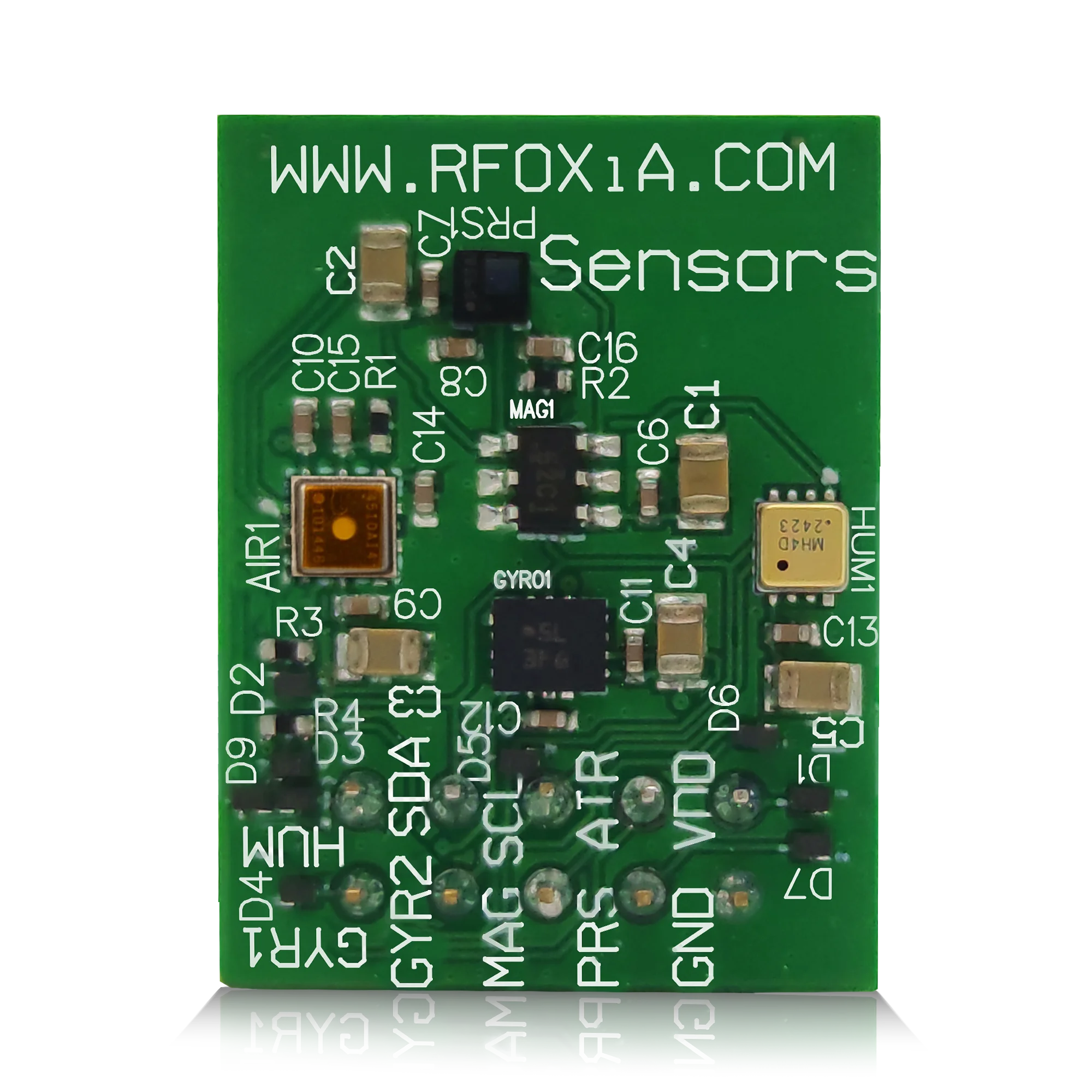
The MultiNav Pro+™ Sensors Module integrates seven professional-grade sensors onto a single 24mm × 18mm PCB, all sharing one I2C bus. Every sensor has its own dedicated address. No conflicts. No extra wiring. No compromises on sensor quality.
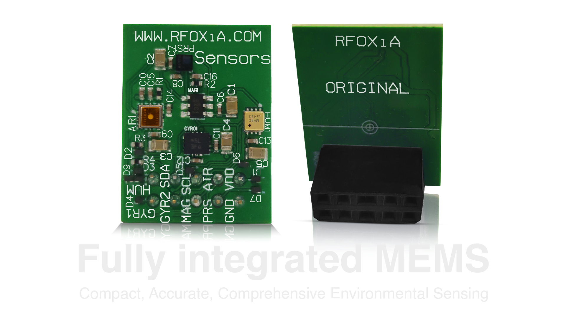
The Seven Sensors on Board
This isn't a board built around generic, low-cost sensor ICs. Every component is sourced from a recognized industry leader:
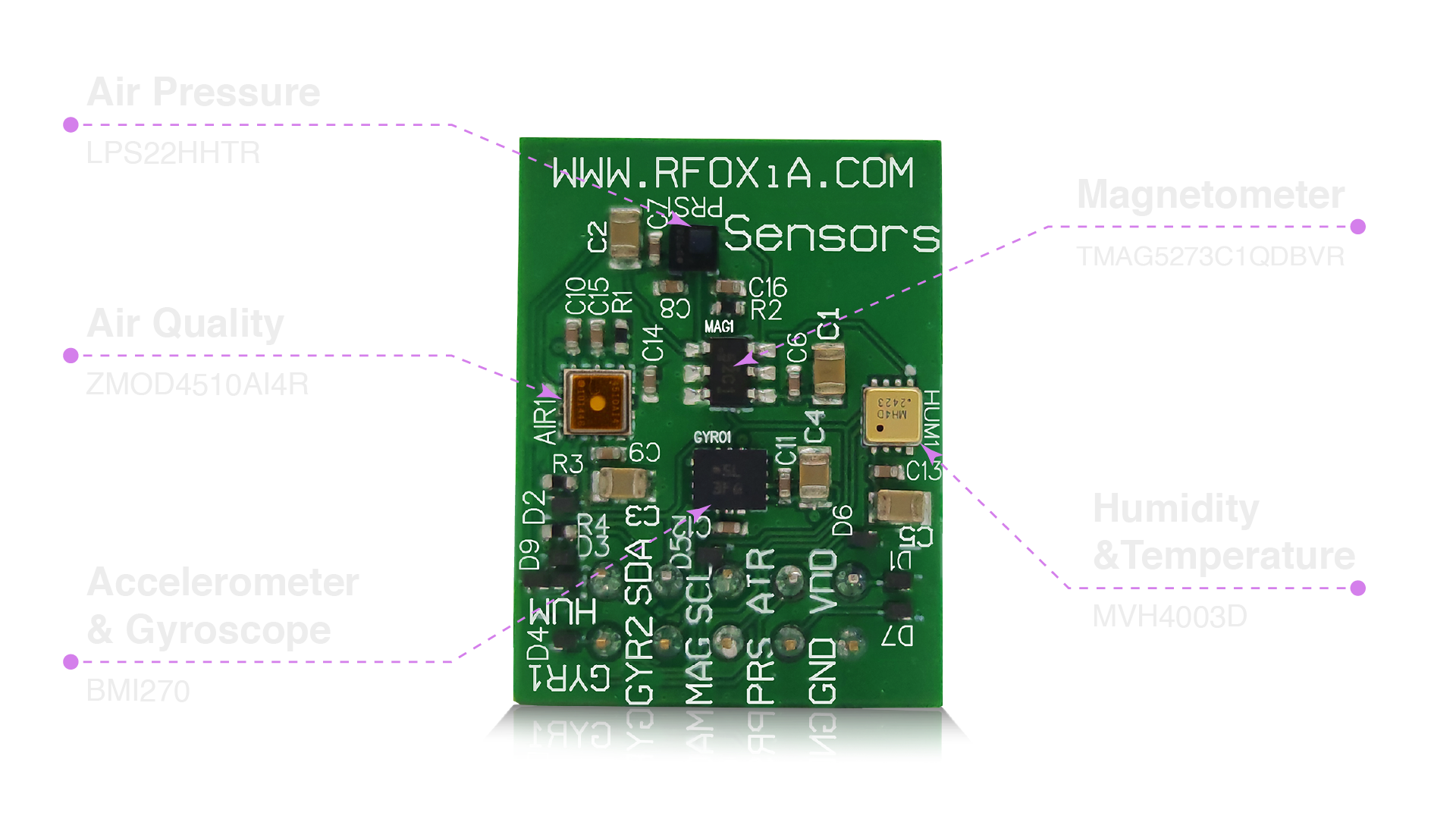
1. Accelerometer & Gyroscope — BMI270 (Bosch Sensortec) The BMI270 is a state-of-the-art 6-axis IMU designed specifically for wearables and drones. It features advanced power management, built-in step detection, and a programmable interrupt engine. Noise density: 180 µg/√Hz on accelerometer, 0.007 °/s/√Hz on gyroscope. This is the same sensor family found in professional flight controllers.
2. Magnetometer — TMAG5273C1QDBVR (Texas Instruments) A 3-axis Hall-effect sensor with 12-bit resolution on each axis. Used for heading, compass bearing, and magnetic anomaly detection. The TMAG5273 offers configurable magnetic range and ultra-low power standby — critical for battery-powered deployments.
3. Air Pressure — LPS22HHTR (STMicroelectronics) Absolute pressure range of 260 to 1260 hPa with an RMS noise of 0.75 Pa. At altitude, this translates to sub-centimeter height estimation — invaluable for drone altitude hold and barometric weather analysis.
4. Humidity & Temperature — MVH4003D (MEMSVision) A MEMS-based humidity and temperature sensor with ±2% RH accuracy and ±0.3°C temperature accuracy. Fast response time makes it suitable for dynamic environmental monitoring rather than slow-moving weather station data.
5. Air Quality — ZMOD4510AI4R (Renesas) The ZMOD4510 is an AI-powered gas sensor designed specifically for outdoor air quality monitoring. It detects nitrogen dioxide (NO₂) and ozone (O₃) — two of the most important urban air quality indicators. Renesas provides a software library for calculating an Air Quality Index (AQI) value directly from the sensor output.
How I2C Multi-Sensor Addressing Works on This Module
One of the most important concepts in any I2C sensor module tutorial is understanding how device addressing prevents bus conflicts.
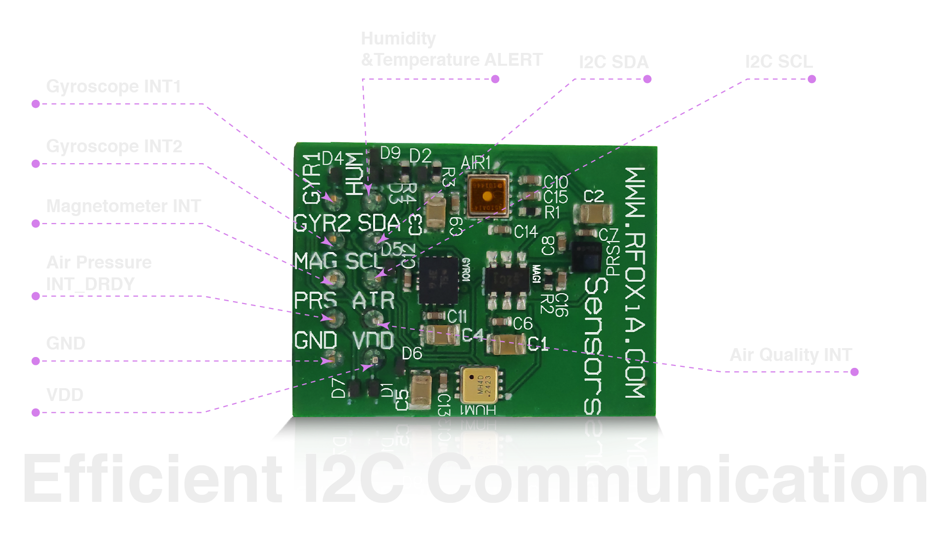
On the MultiNav Pro+™ Sensors Module, every sensor has a dedicated I2C address, pre-configured at the hardware level. You don't need to worry about address conflicts — the PCB design handles it. When your master device initiates communication, it addresses one sensor at a time. All others remain in listen-only mode until called.
Typical I2C Address Map
| Sensor | IC | Typical I2C Address |
|---|---|---|
| Accelerometer / Gyroscope | BMI270 | 0x68 or 0x69 |
| Magnetometer | TMAG5273 | 0x22 |
| Air Pressure | LPS22HH | 0x5C or 0x5D |
| Humidity & Temperature | MVH4003D | 0x44 |
| Air Quality | ZMOD4510 | 0x32 |
Your master device iterates through addresses, initializes each sensor, and then queries them on a polling interval — or configures interrupt pins for event-driven reads on motion sensors.
Pull-Up Resistors
I2C requires pull-up resistors on both SDA and SCL lines. The MultiNav Pro+™ module includes onboard pull-ups, so you don't need to add external resistors when using the module in isolation. If you're combining this module with other I2C devices on the same bus, you'll want to calculate the effective parallel resistance to ensure it stays within the I2C specification (typically 1kΩ–10kΩ depending on bus capacitance and speed).
Wiring the MultiNav Pro+™ Sensors Module
Connecting the module to your microcontroller is a four-wire operation:
| Module Pin | Connect To |
|---|---|
| VCC | 3.3V (recommended) |
| GND | Ground |
| SDA | SDA on your MCU |
| SCL | SCL on your MCU |
Compatible with any I2C-capable microcontroller: STM32, ESP32, Arduino (Uno, Mega, Nano), Raspberry Pi, nRF52 series, and more.
Important: Always power the module at 3.3V unless your specific hardware documentation confirms 5V tolerance. Most modern MEMS sensors operate at 1.8V–3.3V internally.
Firmware Example: Reading All Seven Sensors
Here's a conceptual firmware flow for initializing and reading from the full sensor array. This example targets a generic I2C-capable microcontroller using a C-style pseudocode structure:
// Initialize I2C bus
I2C_Init(400000); // 400kHz Fast Mode

// Initialize each sensor
BMI270_Init(I2C_ADDR_BMI270);
TMAG5273_Init(I2C_ADDR_TMAG5273);
LPS22HH_Init(I2C_ADDR_LPS22HH);
MVH4003D_Init(I2C_ADDR_MVH4003D);
ZMOD4510_Init(I2C_ADDR_ZMOD4510);

// Main loop
while (1) {
    // Motion data
    float accel_x, accel_y, accel_z;
    float gyro_x, gyro_y, gyro_z;
    BMI270_ReadAccel(&accel_x, &accel_y, &accel_z);
    BMI270_ReadGyro(&gyro_x, &gyro_y, &gyro_z);

    // Heading
    float mag_x, mag_y, mag_z;
    TMAG5273_ReadMag(&mag_x, &mag_y, &mag_z);

    // Altitude / pressure
    float pressure_hPa, temp_C;
    LPS22HH_ReadPressureTemp(&pressure_hPa, &temp_C);

    // Humidity
    float humidity_pct;
    MVH4003D_ReadHumidity(&humidity_pct);

    // Air quality
    uint8_t aqi;
    ZMOD4510_ReadAQI(&aqi);

    // Transmit / log all values
    LogSensorData(accel_x, accel_y, accel_z,
                  gyro_x, gyro_y, gyro_z,
                  mag_x, mag_y, mag_z,
                  pressure_hPa, temp_C,
                  humidity_pct, aqi);

    delay_ms(100); // 10Hz polling rate
}
The RFOXiA platform's AI Firmware Builder can generate complete, production-ready firmware for this exact sensor array. You describe your application in plain English — the AI produces the full firmware with initialization sequences, error handling, and data output formatted for your target platform.
Real-World Applications
Understanding the hardware and firmware is only part of this I2C sensor module tutorial. The other part is knowing what to build with it.
Drone Flight Stabilization and Telemetry
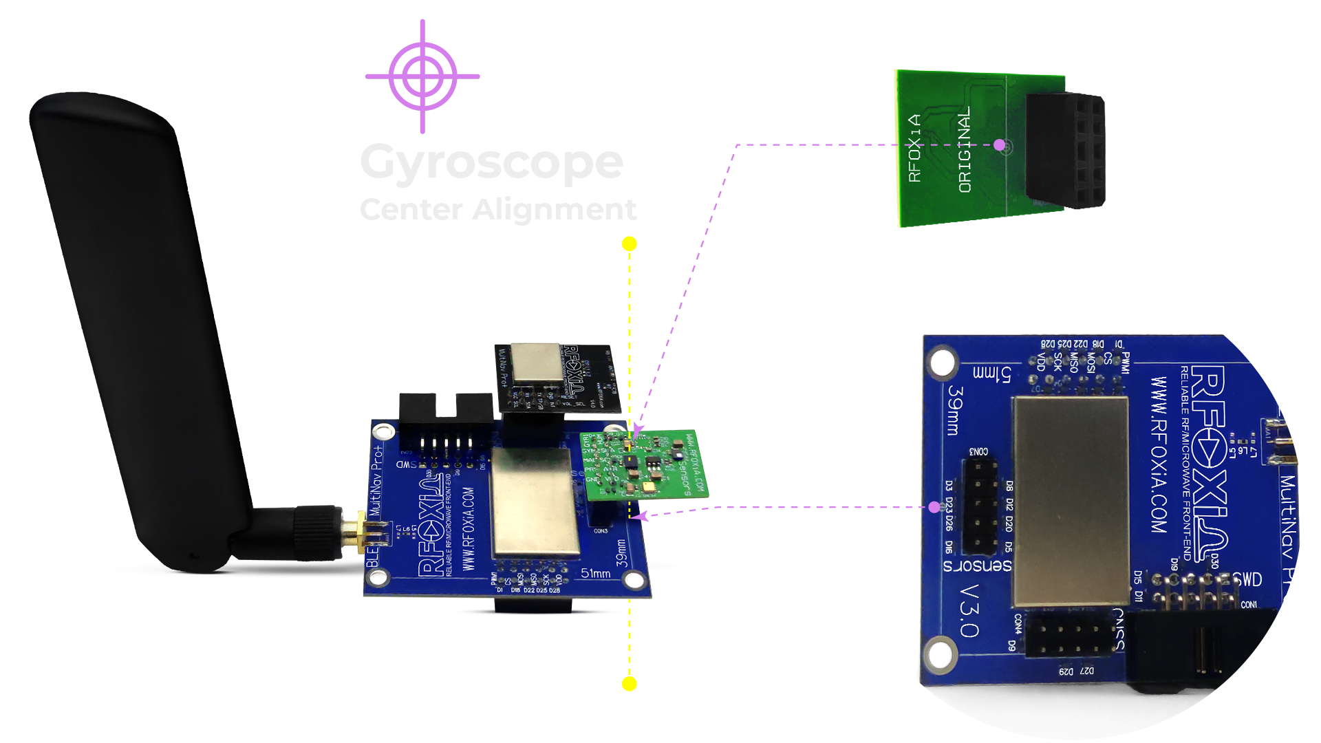
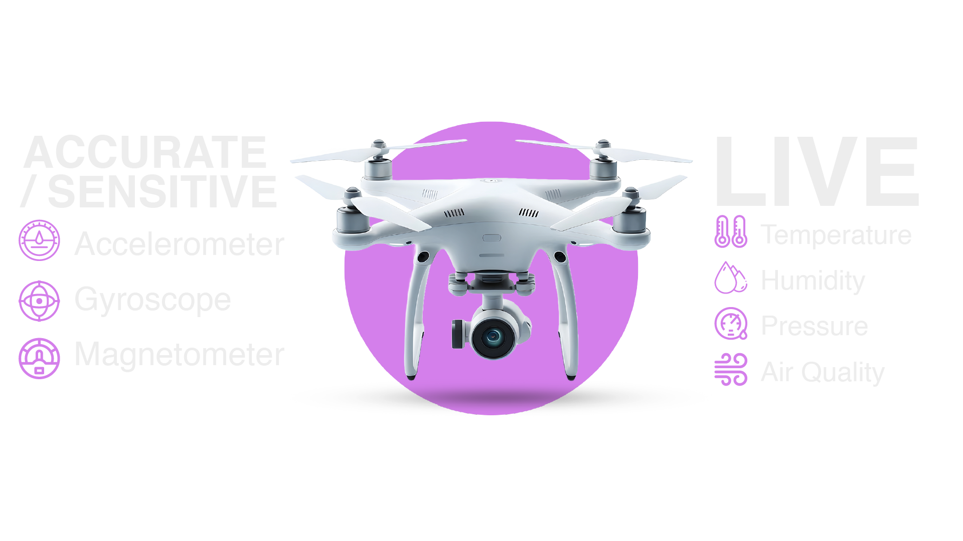
The BMI270 accelerometer and gyroscope deliver the IMU data your flight controller needs for stabilization. Combined with the LPS22HH barometric pressure sensor for altitude hold and the TMAG5273 magnetometer for compass heading, this single module provides the core sensing stack for a professional drone build.
At 24mm × 18mm, it fits on virtually any drone frame without weight or space penalty. Pair it with the RFOXiA GNSS Module (1.5m accuracy, 18Hz fix rate) and BLE Module (up to 20km man-to-drone range) for a complete autonomous navigation and telemetry system.
Environmental Research and Field Monitoring
Deploy the Sensors Module outdoors for continuous environmental monitoring. Temperature, humidity, pressure, and AQI data streams in real time. The ZMOD4510's NO₂ and O₃ detection makes it particularly valuable for urban air quality research, where low-cost sensor networks can provide resolution that fixed government monitoring stations simply cannot match.
IoT Edge Nodes and Smart City Infrastructure
I2C's low pin count and the module's compact footprint make it ideal for edge IoT nodes. A single microcontroller, this sensor module, a power source, and a communication radio (like the RFOXiA BLE Module) creates a complete wireless sensing node that can be deployed at scale.
Robotics and Autonomous Systems
For ground robots and UAVs alike, fused IMU + magnetometer + barometric data creates a rich state estimation input. Whether you're running an EKF (Extended Kalman Filter) for sensor fusion or a simpler complementary filter, the BMI270 and LPS22HH give you the raw data quality that demanding control algorithms require.
The RFOXiA Data Network: Get Paid for Your Sensor Data
This is where the MultiNav Pro+™ Sensors Module goes beyond being just a sensing platform.
RFOXiA operates a live environmental data network. When you deploy a Sensors Module outdoors with GNSS location validation, your verified data — temperature, humidity, pressure, air quality, GPS coordinates — streams to the RFOXiA platform. RFOXiA aggregates and sells this hyper-local, high-resolution data to enterprise buyers: agricultural tech companies, insurance firms, smart city operators, logistics companies, and research institutions.
You earn daily rewards for every verified data session:
- Base rate: $0.08–$0.25/day depending on location and network tier
- Scarcity bonus: Nodes in data-sparse areas earn more
- Uptime bonus: Consistent streaming unlocks higher rates
- Pioneer rate: Early network contributors lock in higher base rates permanently
Your sensor works while you sleep. That's a fundamentally different value proposition than any other sensor module on the market.
Compact Size, Professional Specs
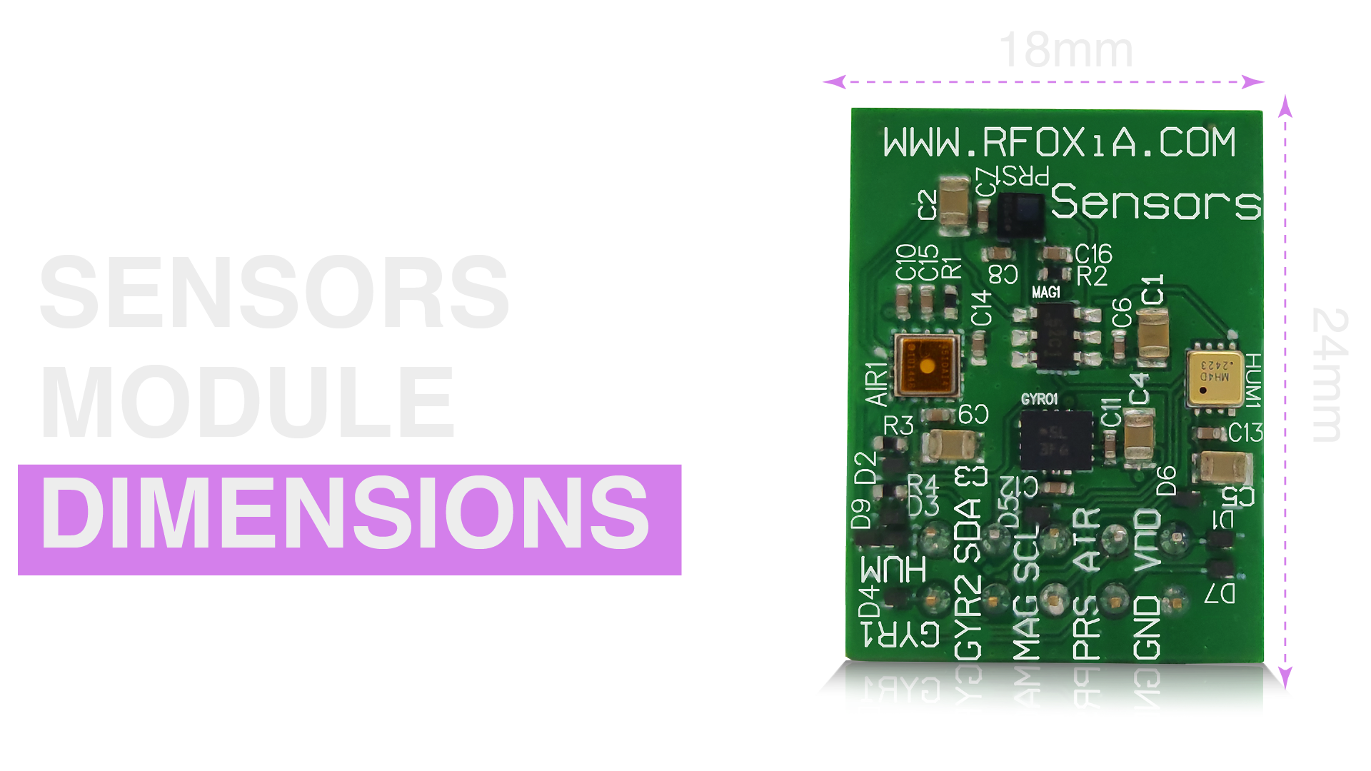
At 24mm × 18mm, the MultiNav Pro+™ Sensors Module is smaller than a postage stamp. It replaces what would otherwise require six or seven individual breakout boards, a nest of wiring, and hours of debugging address conflicts.
For drone builders, wearable developers, and anyone designing compact IoT hardware, this form factor isn't just convenient — it's often the difference between a design that works and one that doesn't fit.
The module is FCC certified, which means it's cleared for deployment in commercial and consumer applications in the United States without additional regulatory work on your end.
Where This Module Fits in the Full RFOXiA Ecosystem
The Sensors Module is one component of a vertically integrated wireless development ecosystem. Here's how the full stack fits together:
| Module | Function | Key Spec |
|---|---|---|
| BLE Module (MultiNav Pro+) | Long-range wireless communication | 5km ground-to-ground, 20km man-to-drone |
| GNSS Module | Precision location | 1.5m accuracy, 18Hz fix rate |
| Sensors Module | Environmental + motion sensing | 7 sensors, I2C, 24mm × 18mm |
| Power/Program Kit | Power management + programming | 5-min charge, 24-hour runtime |
The Developer Bundle combines all four modules into one integrated kit — the only product on the market combining long-range BLE, precision GNSS, multi-sensor environmental monitoring, and professional power management at this price point.
You can explore the RFOXiA Integrated Sensors Module on its own, or pick up the Developer Bundle for the complete ecosystem.
Common I2C Troubleshooting Tips
Even with a well-designed module, I2C issues arise. Here are the most common problems and how to resolve them:
No device found on bus scan:
- Check VCC — confirm 3.3V is present
- Verify SDA and SCL are not swapped
- Run an I2C scanner sketch to confirm bus is active
- Check pull-up resistors if combining with other I2C devices
Intermittent reads / data corruption:
- Reduce I2C clock speed from 400kHz to 100kHz
- Shorten wire lengths — long wires increase capacitance
- Add decoupling capacitors (100nF) close to module VCC pin
Sensor returns zeros after initialization:
- Confirm sensor initialization sequence completed without error
- Check datasheet for required startup delay before first read
- Verify I2C address matches hardware configuration
Address conflict when adding other I2C devices:
- Use an I2C bus scanner to map all addresses on the bus
- Consider an I2C multiplexer (TCA9548A) if conflicts cannot be resolved by address reassignment
AI Firmware Builder: From Idea to Running Code in Minutes
Firmware development is often the biggest bottleneck in hardware projects. Writing initialization sequences, register configurations, and calibration routines for seven different sensor ICs from five different manufacturers would traditionally take days — if you're fluent in C and have all the datasheets open.
RFOXiA's AI Firmware Builder (integrated into the RFOXiA Club Dev Hub) changes that. Describe your application in plain language:
"I need to read accelerometer, gyroscope, magnetometer, pressure, humidity, temperature, and air quality from the MultiNav Pro+ Sensors Module on an STM32, and stream the data over UART at 10Hz."
The AI generates complete, production-ready firmware — initialization sequences, register configurations, error handling, output formatting — with full source code access. What used to take days of datasheet reading and register debugging now takes minutes.

Why the MultiNav Pro+™ Sensors Module Is the Right Choice
Let's be direct about what makes this module different from assembling a sensor stack yourself:
1. No address conflicts by design. Every sensor's I2C address is pre-configured at the PCB level. You don't debug it — it just works.
2. Professional-grade ICs. BMI270, LPS22HH, TMAG5273, ZMOD4510 — these aren't bargain-bin generics. They're the same components in professional drones, medical wearables, and industrial equipment.
3. FCC certified. Ready for commercial deployment without additional regulatory overhead.
4. Ecosystem integration. Works natively with the RFOXiA BLE Module, GNSS Module, Power Kit, Connect app, and data network. Every piece of the stack is designed to work together.
5. Data monetization. No other sensor module pays you back. Deploy it outdoors, contribute verified environmental data to the RFOXiA network, earn daily rewards.
6. AI firmware support. Generate complete firmware for your specific application in minutes through the RFOXiA Club AI Firmware Builder.
For makers, drone builders, IoT engineers, and researchers who need reliable multi-sensor data from a compact, professional-grade platform — this is what you've been waiting for.
Ready to start building? Explore the RFOXiA Integrated Sensors Module and get your module working in your next project today.
Frequently Asked Questions
Q: What microcontrollers is the Sensors Module compatible with? A: Any microcontroller with I2C support — STM32, ESP32, ESP8266, Arduino (Uno, Mega, Nano, MKR), Raspberry Pi, nRF52-based boards, and more. If it has SDA and SCL pins, it works.
Q: Can I use the Sensors Module without the rest of the RFOXiA ecosystem? A: Absolutely. The Sensors Module is a fully standalone I2C sensor board. Use it with any I2C-capable microcontroller and your own firmware. The RFOXiA ecosystem adds connectivity, data monetization, and AI firmware generation — but none of it is required for basic sensor operation.
Q: Does the module require external pull-up resistors? A: The module includes onboard pull-ups for standalone operation. If you're combining it with other I2C devices, calculate effective parallel resistance to stay within I2C specification.
Q: What is the power consumption? A: Power consumption depends on sensor polling rate and active/sleep modes. Each IC supports configurable low-power modes. For precise figures, refer to the individual sensor datasheets (BMI270, LPS22HH, TMAG5273, MVH4003D, ZMOD4510).
Q: Is the module 5V tolerant? A: The module is designed for 3.3V operation. Use a level shifter if connecting to a 5V I2C bus.
Q: How do I access the AI Firmware Builder? A: Sign up for a free RFOXiA Club account at rfoxia.com. New accounts receive a $10 welcome credit. The AI Firmware Builder is in the Dev Hub section of the platform.
Q: Can I contribute sensor data to the RFOXiA network and earn rewards? A: Yes. Deploy the Sensors Module outdoors with GNSS location validation, connect it to the RFOXiA data platform, and earn daily rewards for verified data contributions. Early network participants lock in higher base rates permanently.
Conclusion
This I2C sensor module tutorial has covered the full picture — from protocol fundamentals to sensor-by-sensor hardware specs, from firmware architecture to real-world deployment scenarios and data monetization.
The MultiNav Pro+™ Sensors Module is not a hobbyist breakout board. It's a professional, FCC-certified, ecosystem-integrated sensor array built around industry-leading ICs from Bosch, Texas Instruments, STMicroelectronics, MEMSVision, and Renesas — on a 24mm × 18mm PCB that fits anywhere.
Whether you're building a drone, deploying a field research station, developing a smart city node, or prototyping a wearable — this is the sensor platform that removes the integration headache and lets you focus on what matters: your application.
Explore the RFOXiA Integrated Sensors Module, join RFOXiA Club for free (and collect your $10 welcome credit), and start building with hardware that was engineered to perform.
Written by: Moamen Mohamed LinkedIn