What is a Microstrip?
A Microstrip is a type of electrical transmission line used to transmit RF signals and are commonly fabricated using printed circuit board (PCB) technology. Compared to waveguides, microstrip generally has lower power handling capacity and higher losses due to the fact that it is not enclosed. However, its ease of fabrication and integration make it the preferred choice for many RF and microwave applications.
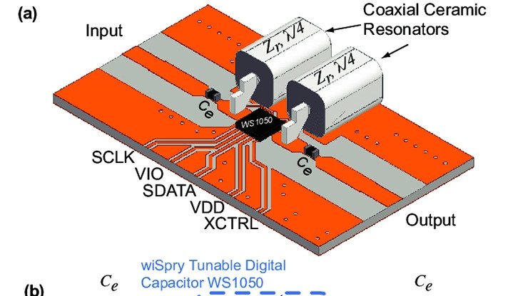
Microstrip Structure
A microstrip transmission line consists of three basic elements:
- Conducting Strip - The signal trace on top of the PCB
- Dielectric Substrate - The insulating material (FR4, Rogers, etc.)
- Ground Plane - The conducting layer on the bottom of the PCB
The characteristic impedance of a microstrip depends on the width of the conducting strip, the thickness and dielectric constant of the substrate, and the thickness of the copper traces.
Understanding Characteristic Impedance
The characteristic impedance (Z₀) of a transmission line is the ratio of voltage to current for a wave traveling along the line. For RF circuits, maintaining the correct impedance is crucial for:
- Minimizing Reflections - Impedance mismatches cause signal reflections
- Maximizing Power Transfer - Proper matching ensures efficient power delivery
- Reducing Signal Distortion - Maintains signal integrity at high frequencies
The standard characteristic impedances in RF design are:
- 50 Ω - Most common for RF applications (antennas, amplifiers, filters)
- 75 Ω - Common for video and cable TV applications
- 100 Ω - Used for differential signals (USB, Ethernet)
Microstrip Impedance Calculation
The Hammerstad and Jensen Formula
The most accurate formula for microstrip impedance calculation was developed by Hammerstad and Jensen and reported in their research paper “E. O. Hammerstad and O. Jensen, Accurate models for microstrip computer-aided design. IEEE MTT-S Dig. 1980, pp. 407–409.”
The accuracy of this model is better than 0.01% for u ≤ 1 and 0.03% for u ≤ 1000, where u = W/h (width-to-height ratio).
Key Parameters
To calculate microstrip impedance, you need:
- W (Width) - Width of the conducting strip
- h (Height) - Thickness of the dielectric substrate
- εᵣ (Dielectric Constant) - Relative permittivity of the substrate material
- t (Thickness) - Thickness of the copper conductor
- f (Frequency) - Operating frequency
Effective Dielectric Constant
The microstrip line has fields in two media: the dielectric substrate and the air above it. The effective dielectric constant (εₑff) accounts for this:
εₑff = (εᵣ + 1)/2 + (εᵣ - 1)/2 × [1 + 12h/W]^(-1/2)
This effective dielectric constant affects both the impedance and the propagation velocity of signals.
Using the RFOXiA Microstrip Calculator
Our free microstrip impedance calculator provides several advantages:
Synthesis Mode
Enter your desired characteristic impedance (e.g., 50Ω) and the calculator determines the required trace width. This saves time compared to trial-and-error design.
Example:
- Target Z₀: 50Ω
- Substrate: FR4 (εᵣ = 4.4)
- Height: 1.6mm (standard PCB thickness)
- Result: W ≈ 3.0mm
Analysis Mode
Enter your PCB parameters (width, height, dielectric constant) and calculate the resulting characteristic impedance.
Example:
- Width: 2.5mm
- Height: 1.6mm
- εᵣ: 4.4
- Result: Z₀ ≈ 53Ω
Additional Information Provided
Our calculator also provides:
- Effective Dielectric Constant (εₑff) - For wave propagation calculations
- Guide Wavelength (λg) - Wavelength of signals in the transmission line
- Electrical Length - Phase delay for a given physical length
- Loss Estimation - Conductor and dielectric losses
- Skin Depth - For high-frequency considerations
Practical Design Considerations
Substrate Material Selection
Common PCB materials and their properties:
FR4
- Dielectric Constant: 4.3-4.7
- Loss Tangent: 0.02
- Cost: Low
- Best for: Frequencies < 2 GHz
Rogers RO4003C
- Dielectric Constant: 3.38
- Loss Tangent: 0.0027
- Cost: Medium
- Best for: Frequencies up to 10 GHz
Rogers RO3003
- Dielectric Constant: 3.00
- Loss Tangent: 0.0010
- Cost: High
- Best for: Frequencies up to 30 GHz
Trace Width Constraints
When designing microstrip lines, consider:
- Minimum Width - Limited by PCB manufacturing capabilities (typically 0.1mm)
- Maximum Width - Higher impedances require narrow traces
- Current Capacity - Wider traces handle more current
- Tolerance - Manufacturing variations affect impedance (±10% typical for FR4)
Frequency-Dependent Effects
At higher frequencies, additional factors become important:
Skin Effect Current concentrates at the surface of conductors, increasing resistance. The skin depth (δ) decreases with frequency:
δ = √(2ρ/ωμ)
Dispersion The effective dielectric constant varies with frequency, affecting propagation velocity.
Radiation Narrow traces can radiate energy, especially at discontinuities.
Common Applications
Antenna Feed Lines
Microstrip transmission lines connect RF amplifiers to antennas, requiring precise 50Ω impedance for maximum power transfer.
RF Filters
Microstrip technology enables compact filter designs using resonant sections of transmission line.
Power Dividers and Combiners
Quarter-wave transformers and Wilkinson dividers use microstrip lines with calculated impedances.
Impedance Matching Networks
Transform source and load impedances using microstrip stubs and transformers.
Design Workflow
Step 1: Specify Requirements
- Operating frequency range
- Characteristic impedance (usually 50Ω)
- PCB stackup (substrate height and material)
Step 2: Calculate Dimensions
Use the RFOXiA Microstrip Calculator to determine trace width:
- Enter target impedance
- Select substrate material and thickness
- Calculate required width
Step 3: Verify Design
- Check manufacturing constraints
- Verify current capacity
- Calculate losses
- Simulate if critical
Step 4: Implement
- Create PCB layout with calculated dimensions
- Include ground vias near transitions
- Maintain consistent spacing from ground
Step 5: Test
- Measure impedance with TDR (Time Domain Reflectometry)
- Verify return loss with VNA (Vector Network Analyzer)
- Check insertion loss across frequency range
Tips for Accurate Microstrip Design
- Use Quality Substrates - FR4 works for low frequencies, but use Rogers or similar for >2 GHz
- Control Trace Width - Maintain ±0.1mm tolerance for consistent impedance
- Ground Plane Coverage - Ensure solid ground plane under microstrip traces
- Avoid Sharp Bends - Use curved or mitered corners to reduce reflections
- Via Stitching - Connect ground planes with vias every λ/20 for multiboard designs
Troubleshooting Common Issues
Impedance Mismatch
Symptom: Poor return loss, reflections Solution: Verify trace width, substrate thickness, and dielectric constant
Excessive Loss
Symptom: Low insertion loss, reduced signal Solution: Use lower-loss substrate, increase trace width, reduce length
Radiation
Symptom: EMI issues, coupling between traces Solution: Add ground plane, increase substrate thickness, use shielding
Conclusion
Understanding microstrip impedance is fundamental to successful RF and microwave PCB design. The Hammerstad and Jensen formulas provide the accuracy needed for professional designs, and our free RFOXiA Microstrip Calculator makes these calculations accessible to engineers and hobbyists alike.
Our calculator offers:
- Accurate calculations based on proven formulas
- Synthesis mode to determine trace dimensions
- Analysis mode to verify existing designs
- Comprehensive information including effective εᵣ, guide wavelength, and more
Whether you’re designing RF filters, antenna feed networks, or high-speed digital circuits, proper microstrip design ensures optimal performance and signal integrity.
Try our free Microstrip Impedance Calculator today and streamline your PCB design workflow!