
Supercapacitor Charger Circuit Design: How the MultiNav Pro+ Power/Program Kit Solves the Biggest Problem in Field Electronics
RFOXiA SuperCapacitor Battery and Programmer Kit
Supercapacitor Charger Circuit Design Reimagined for the Modern Hardware Developer
If you have spent any serious time doing field electronics work — deploying IoT nodes, flying FPV drones, running mobile robotics platforms, or testing embedded systems in real environments — you already know the problem. Batteries fail at the worst possible moment. Charging takes hours. Swapping cells mid-mission is a workflow-breaking interruption that costs time, focus, and data continuity.
The solution most developers reach for is more batteries. Bigger packs. More capacity. But this approach carries its own weight penalty, its own latency, and its own degradation curve. Lithium cells lose capacity after every charge cycle. Their internal resistance climbs over time. They require careful charge management circuitry to prevent thermal runaway. They are sensitive to temperature extremes. And when they finally fail, they fail chemically — sometimes catastrophically.
There is a better architecture. And it starts with understanding supercapacitor charger circuit design at a level deep enough to make real hardware decisions.
This post covers the engineering principles behind supercapacitor charging, explains why supercapacitors outperform lithium batteries for specific professional use cases, and shows exactly how the RFOXiA SuperCapacitor Battery and Programmer Kit implements these principles in a production-ready, FCC-certified package designed for the MultiNav Pro+ ecosystem.
What Makes Supercapacitor Charger Circuit Design Different from Battery Charging
To understand why supercapacitor charger circuit design requires its own engineering approach, you need to understand how supercapacitors store and release energy.
A lithium-ion battery stores energy through electrochemical reactions. Charging causes lithium ions to migrate between electrodes, and the process is fundamentally rate-limited by the kinetics of those reactions. Push too much current and you create metallic lithium plating, internal heating, or pressure buildup. This is why lithium chargers are almost always constant-current / constant-voltage (CC/CV) designs — they ramp current up to a safe level, hold it there until voltage rises to the target, then taper current as the battery approaches full capacity. A full charge cycle typically takes 1 to 4 hours depending on C-rate.
A supercapacitor — or more precisely, an electric double-layer capacitor (EDLC) — stores energy electrostatically rather than electrochemically. Charge accumulates at the interface between a high-surface-area electrode material (typically activated carbon) and an electrolyte. There are no chemical reactions. There is no phase change. There is no thermal runaway risk from overcharging in the same sense as lithium chemistry.
This means supercapacitors can accept charge at dramatically higher rates. The limiting factor is not chemistry — it is the resistance of the circuit delivering that charge. A well-designed supercapacitor charger circuit can deliver very high current at the beginning of the charge cycle when the capacitor voltage is near zero, and naturally taper as the capacitor voltage rises toward the supply voltage. In a simplified model, the charge current follows:
I(t) = (V_supply - V_cap) / R_total
Where R_total includes the source impedance, the charge circuit resistance, and the supercapacitor's equivalent series resistance (ESR). As V_cap rises toward V_supply, the driving voltage differential shrinks, current naturally decreases, and the capacitor approaches full charge asymptotically.
The energy stored in a supercapacitor is:
E = ½ × C × V²
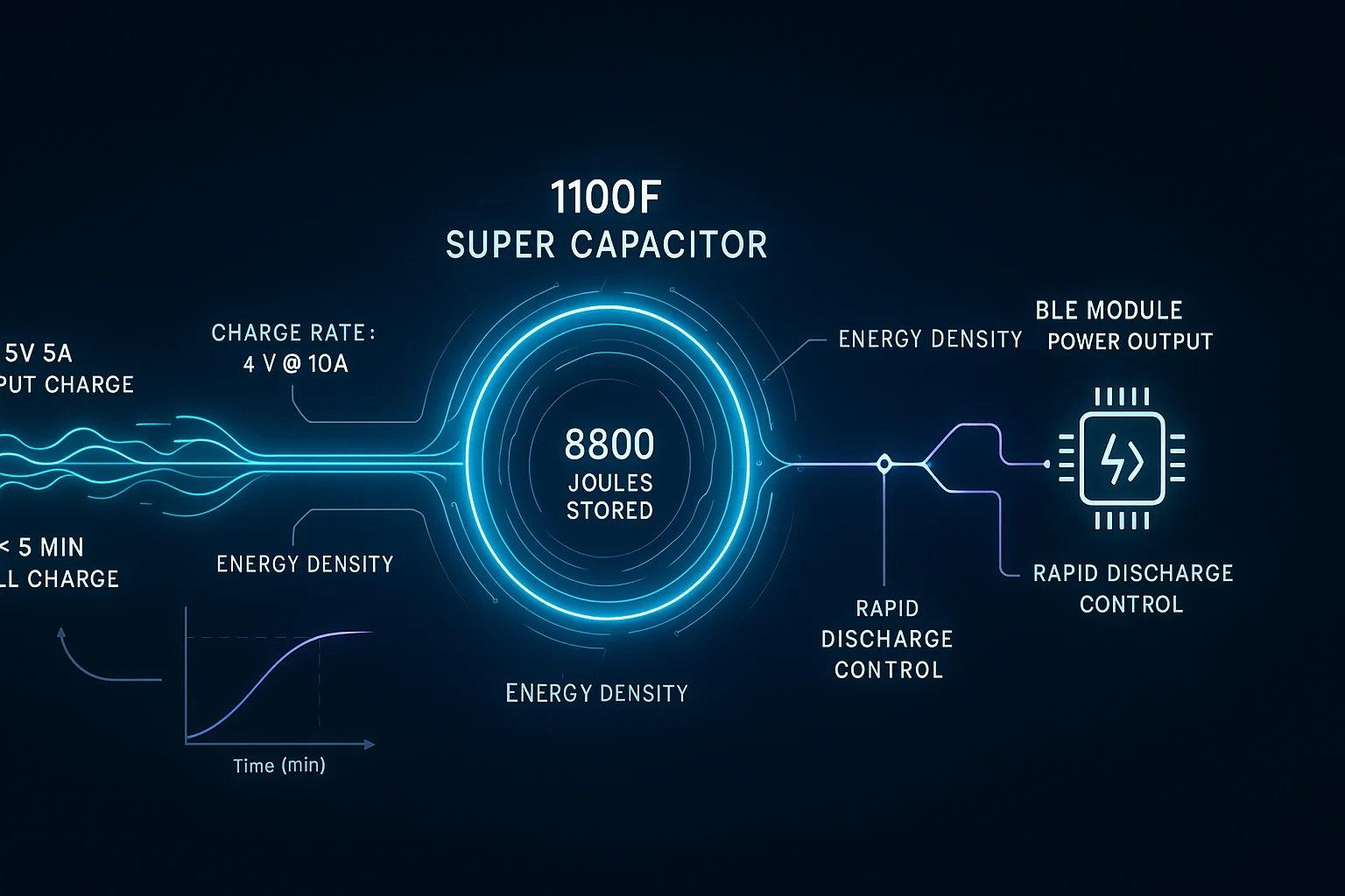
For the MultiNav Pro+ Power Kit's 1100F supercapacitor system operating at a nominal voltage, this yields the 8800 Joules of stored energy specified — enough to power the complete MultiNav Pro+ module stack for a full working day of continuous operation.
The Engineering Challenge: High-Current Charging at 4V / 10A
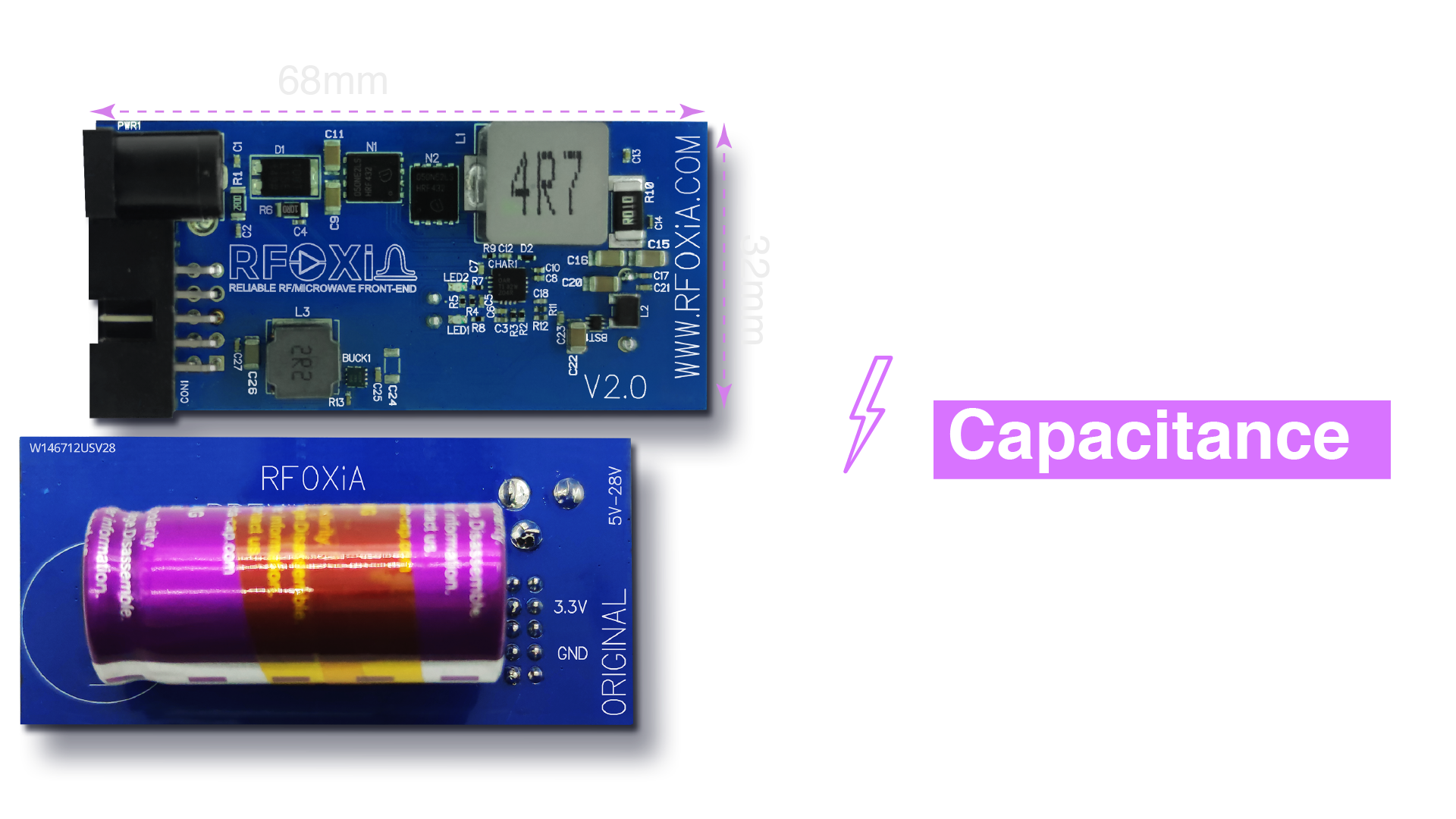
The MultiNav Pro+ Power Kit charges its supercapacitor system at 4V and 10A — that is 40 watts of charge power delivered to the supercapacitor stack. This is what enables the sub-5-minute full charge time that makes the system genuinely practical for field use.
Achieving this safely requires careful supercapacitor charger circuit design with attention to several key parameters:
Inrush current limiting. When a deeply discharged supercapacitor is first connected to a charge source, the voltage differential is at its maximum. Without inrush limiting, the initial charge current can be enormous — potentially damaging both the supercapacitor and the charge source. Professional supercapacitor charger circuit design incorporates controlled current ramp-up using either a dedicated IC or discrete MOSFET-based current limiting.
Voltage regulation accuracy. Supercapacitors do not have the natural voltage plateau that lithium chemistries exhibit at specific states of charge. The capacitor voltage tracks linearly with state of charge. This means the charge termination voltage must be controlled precisely to avoid overvoltage, which can degrade the electrolyte and reduce cycle life.
Thermal management. At 10A charge current, I²R losses in the circuit components generate real heat. PCB trace sizing, component selection (particularly MOSFETs and sense resistors), and thermal relief strategies are all part of the design equation.
Balancing for series capacitor stacks. To achieve higher operating voltages, supercapacitors are connected in series. Individual cells in a series stack will charge at slightly different rates due to manufacturing tolerances in capacitance and ESR. Without active or passive balancing, cells can be driven into overvoltage while others remain undercharged. The MultiNav Pro+ Power Kit's design incorporates balancing to ensure uniform charge distribution across the 1100F stack.
Why 1100F and 8800 Joules? The Energy Budget Behind the Design
The choice of 1100F supercapacitor capacity was not arbitrary. It was derived from a real power budget analysis of the MultiNav Pro+ module ecosystem.
The complete MultiNav Pro+ stack — BLE Module, GNSS Module, and Sensors Module running simultaneously with active RF transmission and GPS fix — draws a measurable average current. Sizing the supercapacitor to deliver 8800 Joules provides the working day runtime claimed, with appropriate headroom for peak current draws during RF transmission bursts.
This is one of the most important aspects of practical supercapacitor charger circuit design that gets overlooked in purely theoretical treatments: you design backwards from the load requirements, not forward from an arbitrary capacitor size. The MultiNav Pro+ Power Kit was designed to match its power source precisely to the power demand of a specific, known workload.
The High-Power Charging Adapter: Source Impedance and the Delivery Chain
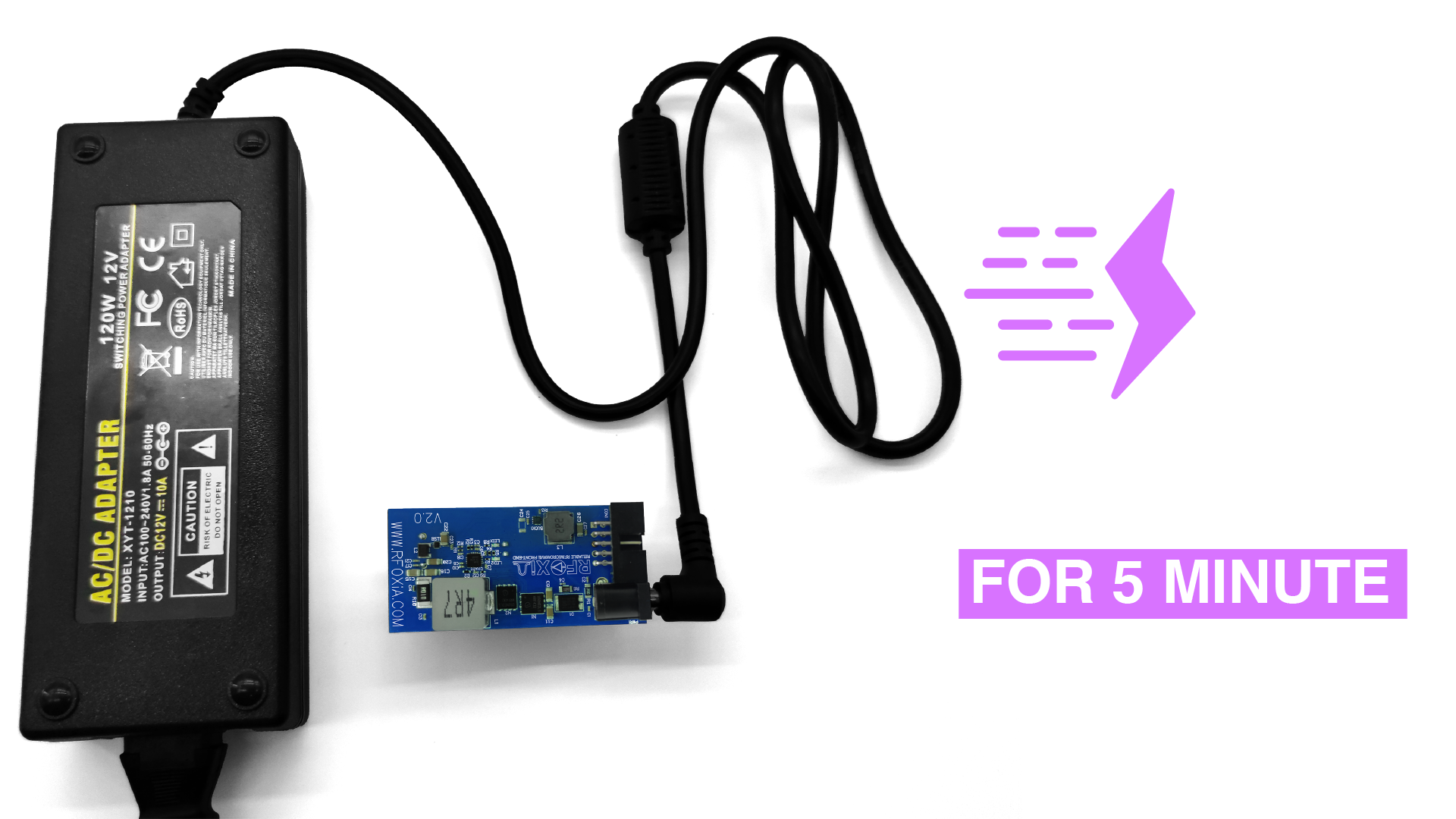
The included 12V 5A adapter is the upstream source for the charge circuit. The on-board supercapacitor charger circuit steps this 12V / 5A input down to 4V / 10A output — performing a voltage step-down with a simultaneous current step-up, consistent with power conversion at roughly constant efficiency.
This is a buck converter topology operating in high-current mode. Key design considerations include:
- Synchronous rectification for efficiency — at these current levels, a diode rectifier would dissipate significant power as heat
- Inductor sizing for the switching frequency and current ripple requirements
- Output capacitor selection to manage voltage ripple at the supercapacitor terminals during charge
- Current sense accuracy for closed-loop charge current regulation
The 12V input also provides meaningful headroom above the 4V charge voltage, giving the converter sufficient differential to maintain regulation and efficiency across the full charge cycle even as the supercapacitor voltage rises.
All-Day Power for the Complete Module Stack
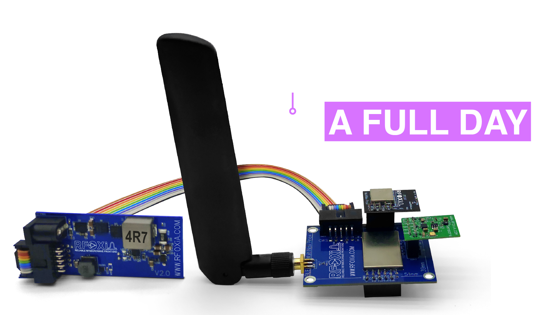
One of the most practically significant specifications of the MultiNav Pro+ Power Kit is its ability to power not just the BLE Module in isolation, but the complete MultiNav Pro+ ecosystem — BLE Module, GNSS Module, and Sensors Module — for a full working day.
This matters because real deployments are not single-module deployments. A drone running the BLE Module for long-range telemetry also needs the GNSS Module for precise positioning and the Sensors Module for environmental data logging. A field research node needs all three running simultaneously. A robotics platform needs the sensor fusion that only comes from all modules active.
The 8800 Joules of stored energy in the 1100F supercapacitor system provides enough capacity to run this multi-module workload through a full day of field operation — and recharges completely in under 5 minutes when you return to base. No waiting. No swapping. No mission-critical power interruption.
For developers building systems that contribute to the RFOXiA data network — streaming verified environmental data from the Sensors Module with GNSS location validation — uninterrupted uptime directly translates to higher daily earnings. Every hour of verified continuous data streaming is an hour of passive income. The Power Kit is not just a convenience feature; it is a revenue enabler.
The Integrated STLink Programmer: Development Without the Workflow Tax
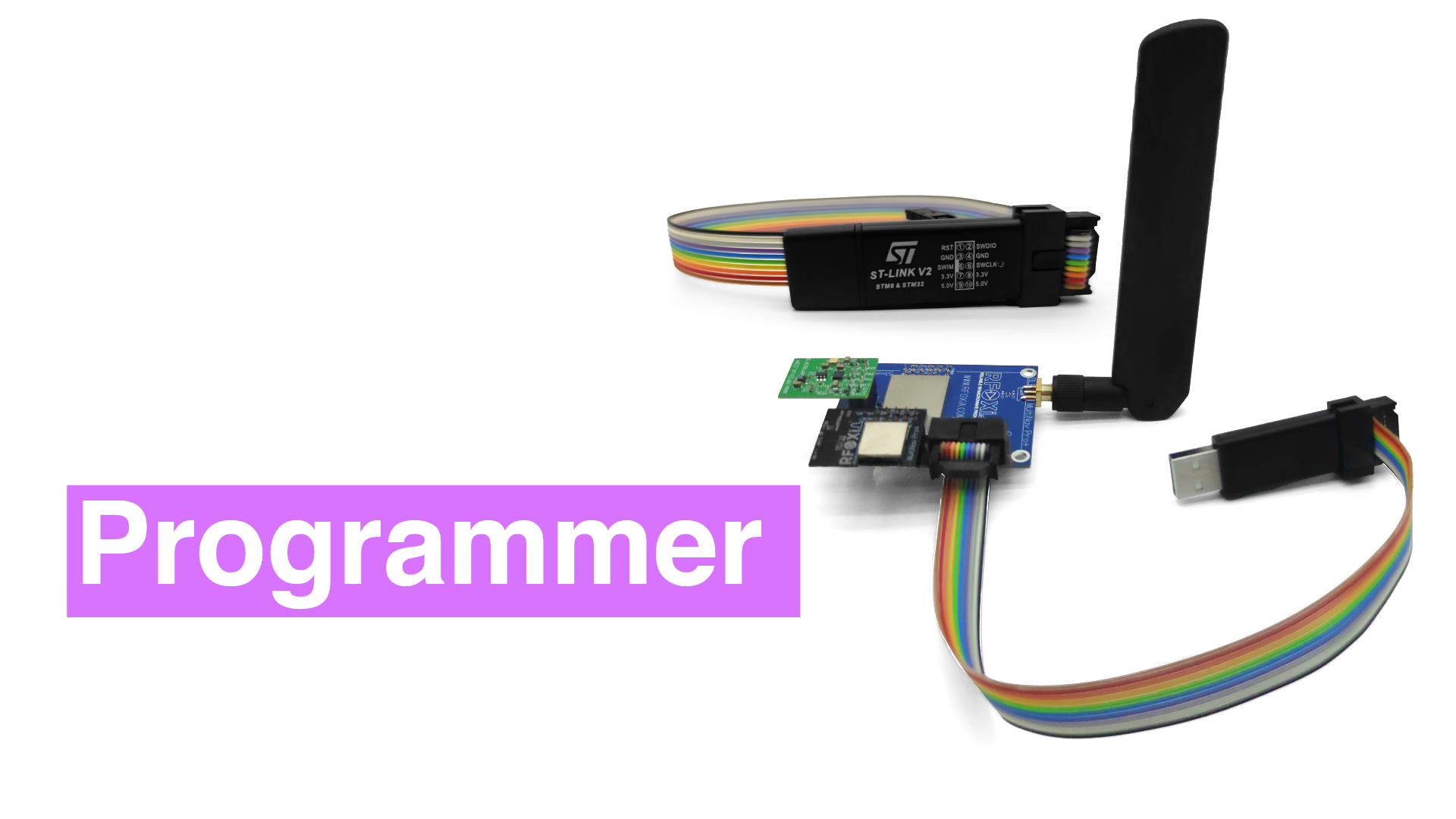
Embedded in the Power/Program Kit alongside the supercapacitor power system is an integrated STLink programmer interface — the standard debug and programming tool for STM32 microcontrollers, which power the MultiNav Pro+ BLE Module (STM32WB07).
This integration is deliberate. The STLink is the hardware bridge between your development environment and your firmware. Without it, you cannot:
- Flash new firmware builds to the BLE Module
- Step through firmware execution with a hardware debugger
- Inspect register states and memory in real time
- Use the RFOXiA AI Firmware Builder's generated code in a live debugging session
Having the STLink integrated into the same kit as the power system means your development bench stays clean. One kit. One cable run. Power and programming, unified.
The MultiNav Pro+ BLE Module's open-source firmware lives on GitHub at https://github.com/RFOXiA/MultiNav-Pro-Long-Range-BLE-Module-Firmware-STM32WB07. The STLink interface in the Power Kit is the direct hardware path for deploying your customized firmware — whether you wrote it from scratch or generated it with the RFOXiA AI Firmware Builder in the Club Dev Hub.
Complete Connectivity: Ribbon Cables and System Integration
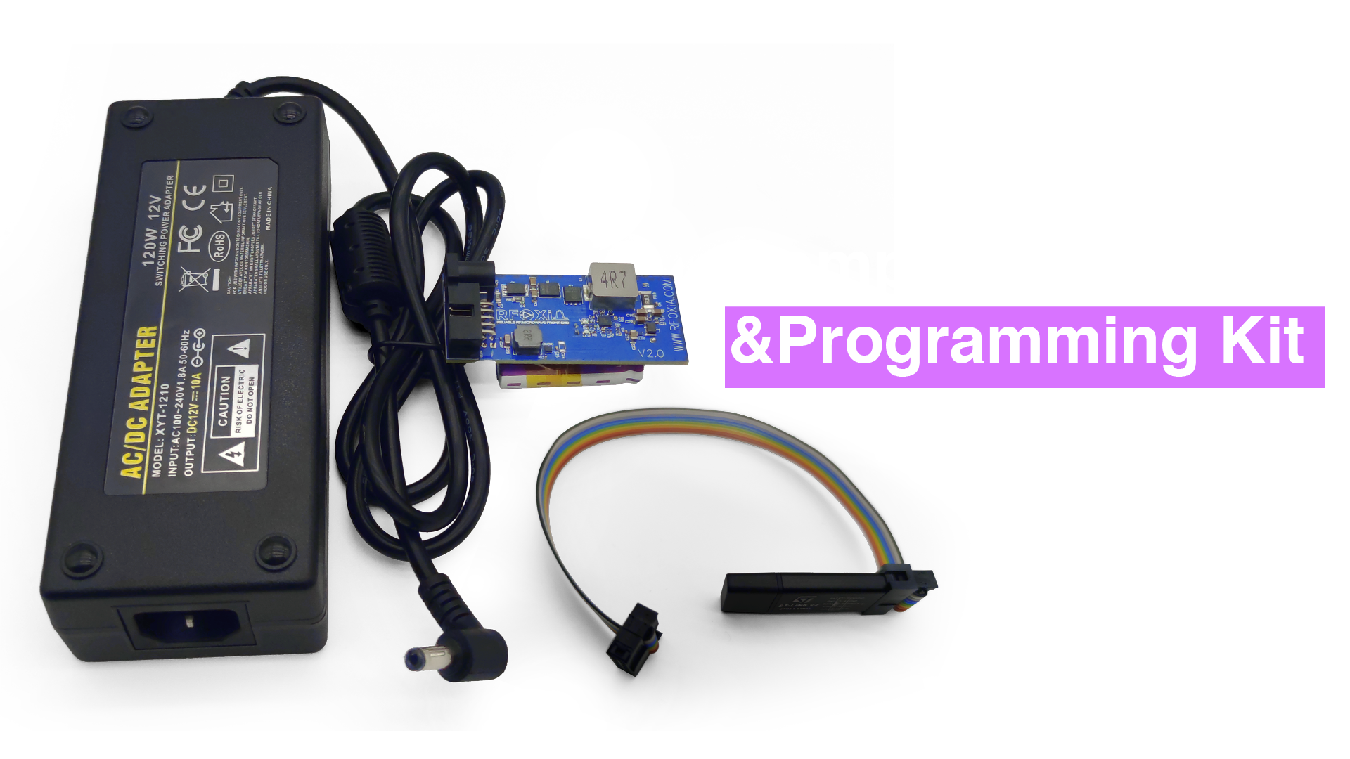
The Power/Program Kit ships with the complete cable set needed to integrate the entire MultiNav Pro+ ecosystem. Flat ribbon cables connect the BLE Module to the power module and the STLink programmer to the BLE Module — providing a clean, mechanically stable connection that is appropriate for both bench development and field deployment.
Flat ribbon cables are the right choice for this application. They maintain consistent impedance across conductors, are mechanically predictable in routing (unlike loose wire harnesses), and have a low profile that fits within compact enclosures. For developers packaging the MultiNav Pro+ stack into a custom drone frame or field enclosure, the ribbon cable geometry makes integration significantly easier than discrete wire connections.
Supercapacitor vs. Lithium Battery: When to Choose Each
Supercapacitors are not universally superior to lithium batteries. Understanding the trade-offs is part of professional supercapacitor charger circuit design work.
Choose supercapacitors when:
- Charge speed is mission-critical (sub-5-minute recharge is only achievable with supercapacitors)
- Cycle life matters — supercapacitors can sustain 500,000+ charge cycles vs. 300-1000 for lithium
- Temperature range is extreme — supercapacitors operate reliably from -40°C to +65°C without the capacity degradation lithium cells suffer in cold
- Safety is paramount — no chemical reaction means no thermal runaway risk
- Instantaneous high current delivery is needed — supercapacitors have very low ESR and can deliver peak currents without voltage sag
Choose lithium batteries when:
- Energy density by weight is the primary constraint (lithium stores more energy per kilogram)
- Cost is the dominant factor for high-volume consumer products
- Very long runtimes from a single charge are required without recharge opportunity
For the MultiNav Pro+ use case — professional field deployment, frequent recharge cycles, all-day runtime from a single fast charge, wide temperature range operation — the supercapacitor architecture is the technically correct choice. The RFOXiA SuperCapacitor Battery and Programmer Kit was designed around this trade-off analysis, not simply as a differentiating feature.
FCC Certification and Professional Deployment
All MultiNav Pro+ modules, including the Power/Program Kit, carry FCC certification. This is not a minor compliance checkbox — it is the credential that separates professional hardware from hobbyist electronics.
FCC certification means:
- The device has been tested and verified to meet radiated and conducted emissions limits
- It is legal to operate in the United States without restriction
- It qualifies for listing on professional distribution channels including DigiKey, Mouser, and element14
- Buyers in enterprise and institutional contexts can proceed with procurement confidence
For developers integrating the MultiNav Pro+ Power Kit into systems destined for regulatory environments — commercial drone operations, environmental monitoring deployments, industrial IoT installations — FCC certification is a non-negotiable requirement. RFOXiA delivers it across the entire product line.
Practical Supercapacitor Charger Circuit Design Principles for Your Own Projects
If you are designing your own supercapacitor charger circuit for a custom application, the following principles apply broadly:
Calculate your energy budget first. Determine your load power draw and required runtime. Use E = ½CV² to determine the minimum capacitance at your target operating voltage.
Design for controlled inrush. Never connect a discharged supercapacitor directly to a voltage source without current limiting. Use a dedicated IC (LTC3350, MAX1672, or similar) or a discrete soft-start MOSFET circuit.
Size your PCB traces and components for peak charge current, not average current. At 10A, a 1mm PCB trace will heat significantly. Use trace width calculators and consider copper pours for high-current paths.
Include per-cell balancing for series stacks. Passive balancing (resistors in parallel with each cell) is simpler but less efficient. Active balancing (switched capacitor or inductor-based) is more efficient but more complex.
Validate thermal performance under load. Measure temperatures at all power components during a full charge cycle at maximum ambient temperature.
Consider the discharge circuit as carefully as the charge circuit. The supercapacitor's terminal voltage drops as it discharges. Your load circuit must tolerate this voltage variation — or you need a DC-DC converter on the output to regulate a stable supply voltage to your load.
The MultiNav Pro+ Power Kit addresses all of these design points in a production-validated, FCC-certified implementation. For developers who want to learn from a real working implementation, the kit itself is a hardware reference for professional supercapacitor charger circuit design.
Who Needs the MultiNav Pro+ Power/Program Kit
The Power Kit is the right tool for:
- Drone builders and FPV pilots running MultiNav Pro+ BLE Modules for long-range telemetry and control, who need reliable power through long flying sessions and fast turnaround between flights
- Field researchers deploying environmental monitoring nodes that need all-day uptime and rapid recharge between site visits
- IoT developers building and testing firmware who need integrated programming capability alongside clean, stable power
- RFOXiA data network contributors who need maximum uptime from their sensor nodes to maximize verified data streaming hours and daily reward earnings
- Robotics engineers running MultiNav Pro+ for wireless control and sensor fusion who cannot afford power interruptions mid-operation
At $119 for a complete power and programming solution — supercapacitor system, high-power charging adapter, STLink programmer, and full cable kit — the MultiNav Pro+ Power/Program Kit delivers professional infrastructure at a price that respects the reality of hardware development budgets.
The Complete Ecosystem Picture
The Power/Program Kit is one part of a vertically integrated development ecosystem. Combined with the MultiNav Pro+ BLE Module (5km ground range, 15-20km man-to-drone), GNSS Module (1.5m accuracy, 18Hz fix rate), and Sensors Module (7 environmental sensors, data network compatible), the Developer Bundle gives you everything needed to build, deploy, and earn from long-range wireless systems.
The RFOXiA Club platform — with its AI Firmware Builder, live data visualization, community Dev Hub, and rewards dashboard — wraps the hardware in software infrastructure that compresses development time from months to hours.
If you are ready to eliminate power anxiety from your development workflow and invest in a supercapacitor charger circuit design that actually delivers on its specifications, the RFOXiA SuperCapacitor Battery and Programmer Kit is available now, FCC certified, in stock, and ready to ship.
Specifications Summary
| Parameter | Value |
|---|---|
| Supercapacitor Capacity | 1100F |
| Stored Energy | 8800 Joules |
| Full Charge Time | < 5 minutes |
| Runtime (full module stack) | Full working day |
| Charge Input | 12V / 5A (adapter included) |
| Charge Output | 4V / 10A |
| Programmer Interface | STLink (STM32 compatible) |
| Included Cables | Flat ribbon cables for full stack integration |
| Certification | FCC certified |
| Price | $119 |
Power is not a constraint. It is an engineering problem with an engineering solution. The MultiNav Pro+ Power/Program Kit is that solution — built by hardware developers, for hardware developers, around the right technology for the job.
Written by: Moamen Mohamed LinkedIn