
Supercapacitor Charging Circuit Tutorial: How to Power Your Wireless Projects Without Battery Headaches
RFOXiA SuperCapacitor Battery and Programmer Kit
Supercapacitor Charging Circuit Tutorial — The Definitive Guide for Hardware Developers
If you have ever deployed a wireless sensor node in the field, operated a long-range BLE module on a drone, or run a robotics project through a full day of testing, you already know the pain: batteries die at the worst possible moment. They degrade over charge cycles, they take hours to recharge, and in cold environments they lose capacity unpredictably. For professional hardware developers, this is not an inconvenience — it is a fundamental design constraint that shapes every project decision.
This supercapacitor charging circuit tutorial is written for engineers, makers, drone builders, and IoT developers who are done compromising on power. We are going to cover the principles behind supercapacitor-based power systems, how a charging circuit actually works at the component level, and then show you a real, production-ready implementation that ships today — the RFOXiA SuperCapacitor Battery and Programmer Kit.
By the end of this guide you will understand why supercapacitors are replacing batteries in professional embedded deployments, how to design or evaluate a charging circuit for your own application, and how to power a complete wireless development stack — BLE module, GNSS, and environmental sensors — for a full 24 hours on a single 5-minute charge.
Why Supercapacitors Instead of Lithium Batteries?
Before we get into the circuit design, it is worth being precise about what makes supercapacitors fundamentally different from lithium-ion or lithium-polymer batteries — and where each technology belongs.
Energy Density vs. Power Density
Lithium batteries win on energy density. A good 18650 cell stores roughly 250 Wh/kg. A supercapacitor stores somewhere between 5 and 15 Wh/kg. On paper, batteries hold far more energy per gram.
But power density tells a different story. Supercapacitors can deliver and absorb enormous current spikes without degradation. A lithium cell stressed with a high-current pulse ages faster and risks thermal runaway. A supercapacitor handles the same pulse without flinching, and it does so for hundreds of thousands of cycles versus a battery's typical 300-1000 full cycles.
For wireless hardware developers, this means:
- RF transmission bursts — BLE radios draw sharp current spikes during transmission. Supercapacitors absorb these spikes cleanly, preventing the voltage sag that corrupts packets on battery-powered systems.
- Cold weather operation — Supercapacitors lose far less capacity at low temperatures compared to lithium chemistry.
- Charge speed — A supercapacitor can accept charge as fast as you can deliver it safely. A lithium cell requires a carefully managed CC-CV (constant current, constant voltage) profile over hours.
- Longevity — In a deployment that cycles power daily, a supercapacitor system will outlast a lithium battery by years.
Where Supercapacitors Make Sense
Supercapacitors are not always the right answer. For applications requiring multi-day autonomous operation — weather buoys, remote agricultural sensors — lithium still wins on raw energy capacity. But for applications where:
- The device is recharged daily or more frequently
- Charge speed is operationally critical
- Peak current handling matters (RF, motor drivers)
- Cycle life is a design requirement
- Temperature extremes are expected
...a supercapacitor bank is almost always the superior engineering choice.
Supercapacitor Charging Circuit Tutorial: Core Principles
A supercapacitor charging circuit has one job: move energy from a source into the capacitor bank safely, efficiently, and at the maximum rate the capacitor can absorb without damage.
Here is what you need to understand to design or evaluate one correctly.
1. Voltage Limits and Cell Balancing
Individual supercapacitor cells are typically rated to 2.7V maximum. Exceed this even briefly and you accelerate aging dramatically. Most practical systems require more than 2.7V to power embedded electronics (which typically run at 3.3V or 5V), so cells are connected in series.
Two cells in series gives you 5.4V maximum — enough to power a 3.3V system through a regulator with headroom. But series connection introduces a critical problem: cell voltage imbalance. If one cell charges faster than its neighbor, it will hit its 2.7V limit while the other is still at 2.5V, and the overcharged cell degrades rapidly.
Balancing circuits solve this problem. Passive balancing uses resistors across each cell to bleed down faster-charging cells. Active balancing uses switched converters to redistribute charge. For most embedded applications, passive balancing is adequate and far simpler.
2. Charging Architecture Options
Direct charging from a current-limited source: The simplest approach. You set a current limit at your source and let the supercapacitor charge naturally. Since V = Q/C and Q increases linearly with constant current, voltage rises linearly. This is clean, predictable, and easy to implement.
A 1100F supercapacitor bank charged at 10A will reach 4V in: time = C × ΔV / I = 1100 × 4 / 10 = 440 seconds ≈ 7.3 minutes
With balancing headroom and circuit overhead accounted for, a real system charging at 10A into 1100F targets 4V in approximately 5 minutes. This is exactly the design point of the RFOXiA Power/Program Kit — and it is not a coincidence. It represents careful engineering around the charge equation.
Buck converter charging: A switching buck converter steps down a higher voltage source to the target capacitor voltage while regulating current. Efficient (85-95% typically), generates less heat than linear regulation, and allows precise current control throughout the charge cycle.
Linear regulator charging: Simple, low noise, but dissipates the voltage difference across a pass transistor as heat. Acceptable for small capacitance values or when the voltage difference between source and target is small. Not practical for large banks at high current.
3. Inrush Current Management
When you connect a discharged supercapacitor directly to a voltage source, it draws enormous instantaneous current — theoretically unlimited, practically limited only by source impedance and wiring resistance. This inrush can damage your source, blow protective fuses, and stress the capacitor.
Proper charging circuits always include inrush limiting, either through:
- A series resistor (simple but wastes energy as heat)
- A current-limiting circuit using a MOSFET and sense resistor with feedback (efficient, precise)
- A dedicated supercapacitor charger IC (simplest implementation, many options from Linear Technology, Texas Instruments, and others)
4. Output Regulation
A supercapacitor bank does not maintain a constant voltage — it discharges linearly. A fully charged 4V bank may drop to 2V before the system needs to stop. Your load circuit needs to handle this voltage range, which means:
- A boost converter on the output maintains constant 3.3V or 5V as the bank discharges
- Low-dropout regulators work only when the capacitor voltage is above the output voltage plus dropout margin
- Some microcontrollers and radio modules tolerate a wide supply range and can run directly from the supercapacitor output with appropriate firmware management
Real-World Implementation: The RFOXiA Power/Program Kit
Theory is useful. A working product you can hold in your hand is better. The MultiNav Pro+ Power/Program Kit from RFOXiA is a production implementation of everything described above, engineered specifically for the MultiNav Pro+ wireless development ecosystem.
The 1100F Supercapacitor Bank
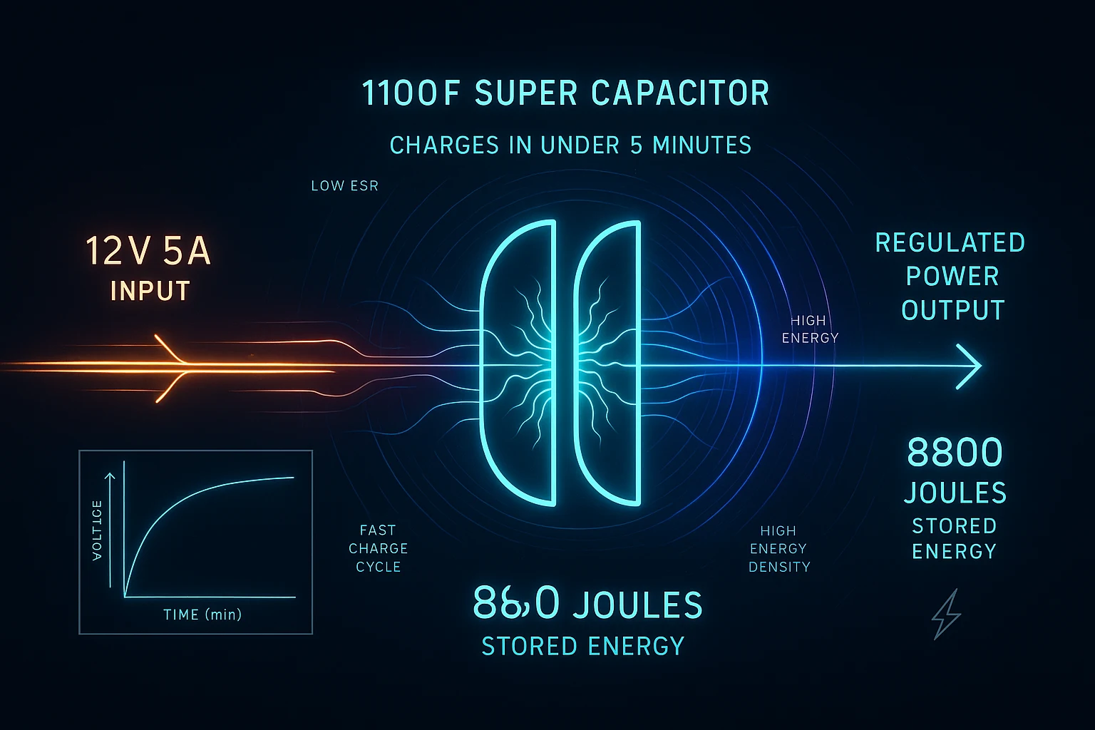
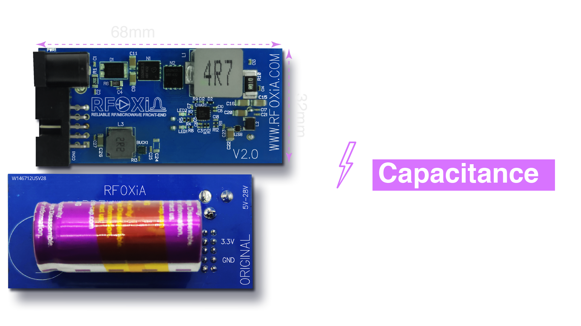
At the heart of the system is an 1100F supercapacitor bank storing 8800 Joules at full charge. To put that in context: 8800 Joules at an average system draw of 100mA at 3.3V (0.33W) gives you approximately 26,000 seconds — over 7 hours — for a single BLE module. The full MultiNav Pro+ stack including BLE, GNSS, and sensors runs efficiently enough that the kit delivers a verified 24-hour runtime under normal operating conditions.
The choice of 1100F is deliberately matched to the 10A charging current from the adapter to hit the 5-minute charge target. This is the core engineering relationship at the center of this supercapacitor charging circuit tutorial: the interplay between capacitance, charge current, and target voltage that determines charge time.
The High-Power Charging Adapter
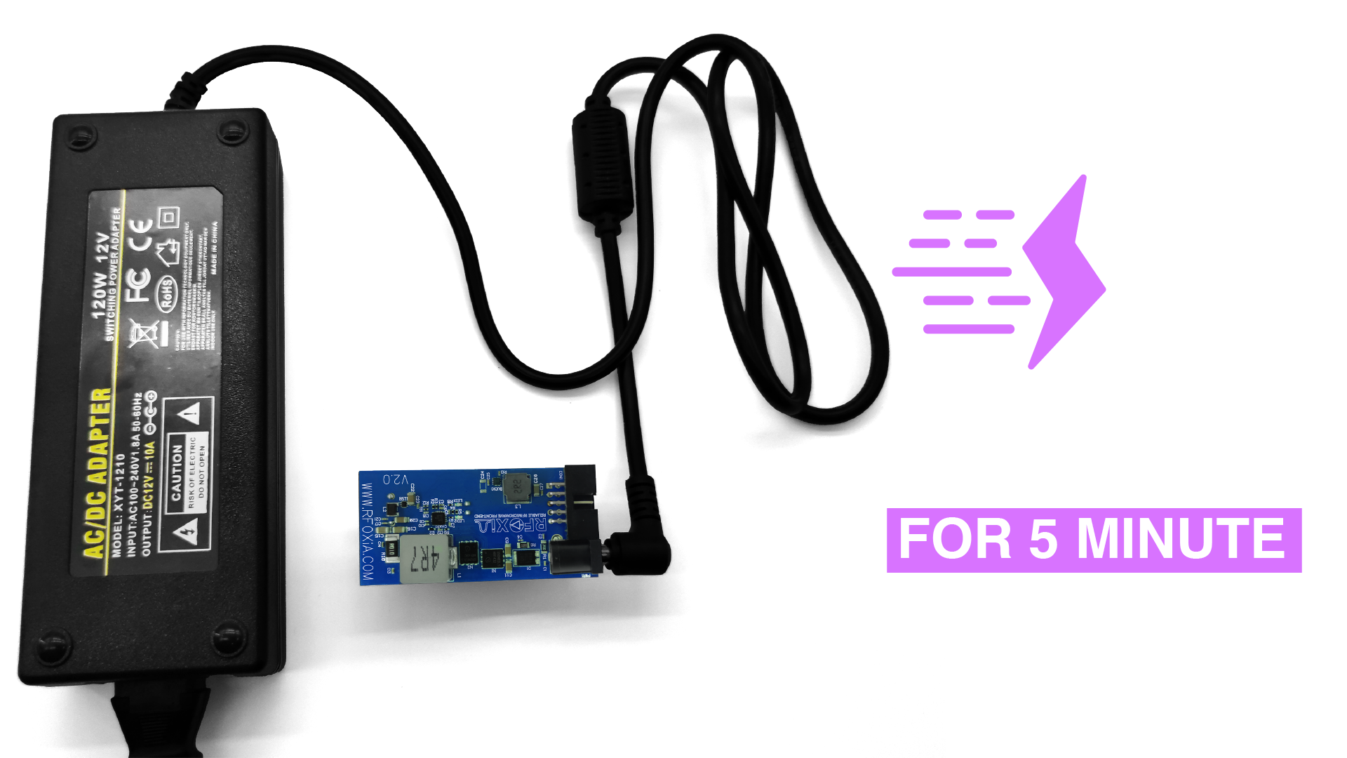
The included adapter delivers 12V at 5A from the wall, which the charging circuit steps down and transforms to 4V at 10A into the supercapacitor bank. The power conversion here is important: 12V × 5A = 60W input, 4V × 10A = 40W into the capacitor, representing approximately 67% conversion efficiency at peak charge — acceptable for the short 5-minute charge window. The circuit is designed for thermal performance during this brief high-current phase.
The adapter specification is not arbitrary. It represents the maximum current a standard charging circuit topology can deliver into this capacitor bank while maintaining safe cell voltages and manageable thermal dissipation. Going higher would require active liquid cooling or a fundamentally different architecture.
24-Hour Runtime Across the Full Module Stack
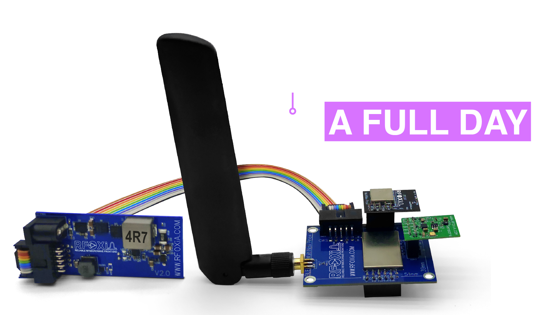
The power kit is designed to drive the complete MultiNav Pro+ ecosystem simultaneously: the long-range BLE module, the 18Hz GNSS module, and the 7-sensor environmental module. Combined, these modules represent a complete wireless development platform capable of real-time location tracking, environmental data streaming, and 20km range control — all from a single supercapacitor charge.
For field researchers, drone operators, and anyone running extended test sessions, this changes the operational calculus entirely. Instead of managing battery swaps or hunting for outlets, you charge once in the morning and work all day.
Integrated STLink Programmer
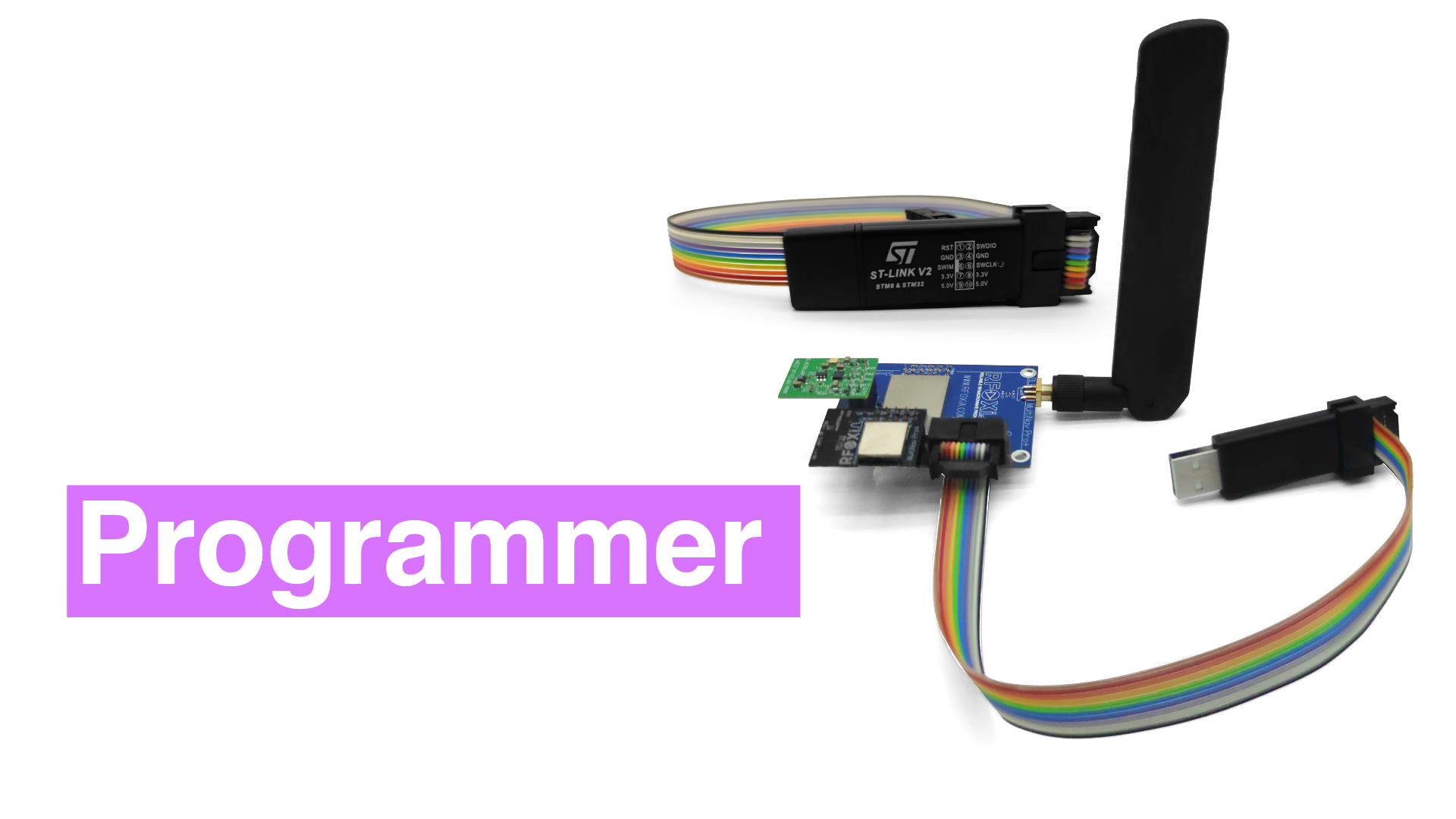
The kit includes an integrated STLink programmer interface designed specifically for the MultiNav Pro+ BLE module. The BLE module runs on an STM32WB07 microcontroller, and the STLink interface provides full JTAG/SWD access for firmware flashing, debugging, and real-time variable inspection.
This is meaningful for developers working on custom firmware. The RFOXiA AI Firmware Builder (accessible through RFOXiA Club) generates production-ready STM32WB07 firmware from plain-language descriptions, and the STLink programmer in this kit is what gets that firmware onto the module in seconds. No separate programmer to source, no compatibility questions — it is designed and tested together.
Complete Connectivity Kit
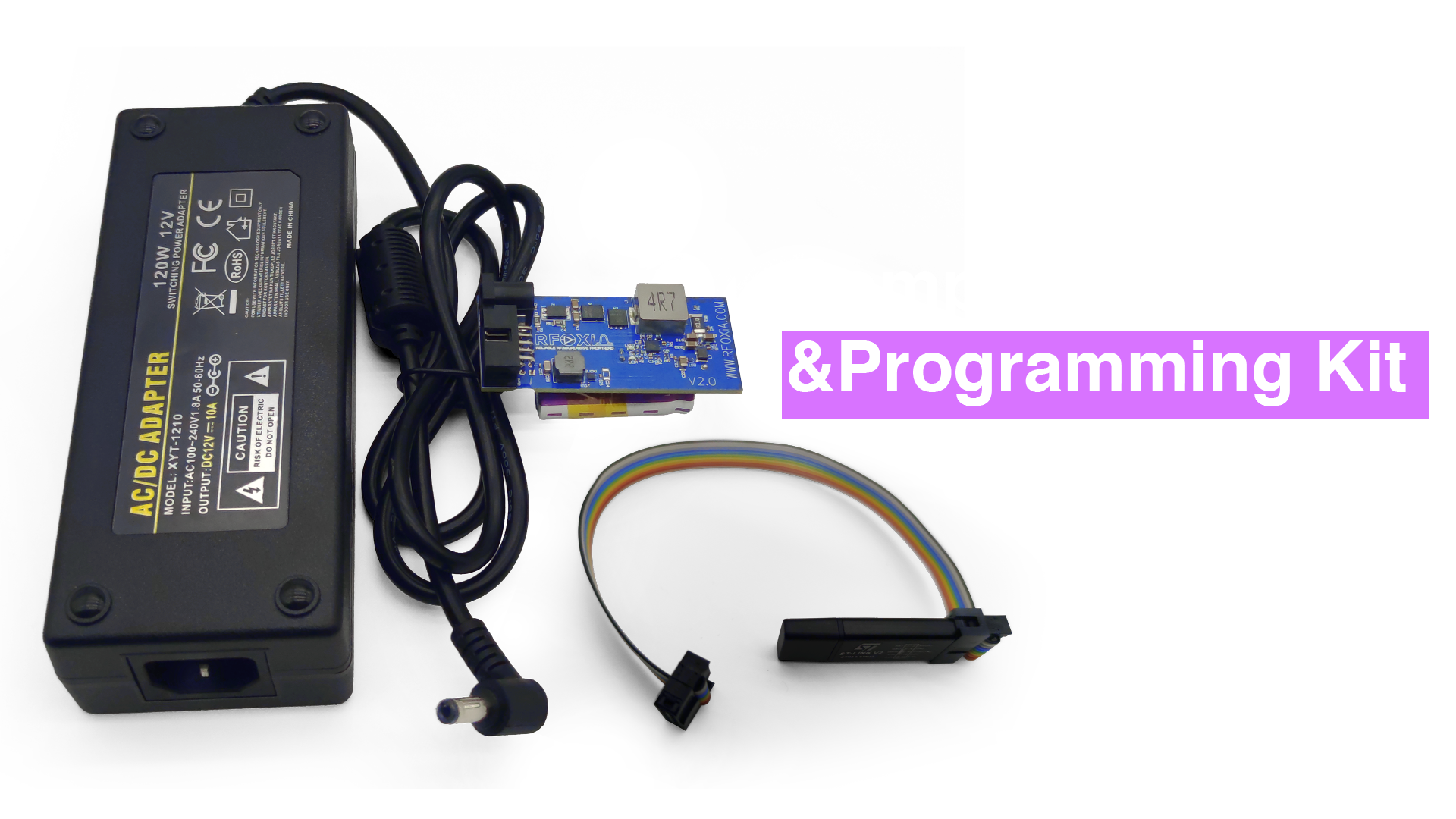
The kit ships with all cables needed to connect the components: flat ribbon cables for BLE module to power module, programmer to BLE module, and all necessary interconnects. In the hardware world, the cables matter. A kit that ships without the right connectors is a kit that sits on a desk while you wait for an order from a parts distributor. RFOXiA ships complete.
Supercapacitor Charging Circuit Design Considerations for Your Own Projects
If you are designing a supercapacitor charging circuit from scratch for a custom application, here are the key decisions you need to make:
Step 1: Define Your Energy Budget
Calculate your system's average power draw. Multiply by your required runtime. This gives you your minimum energy storage requirement in joules (or watt-hours). Then add 20-30% margin for real-world losses.
Step 2: Select Capacitance
E = 0.5 × C × V² gives you stored energy. But you cannot discharge a supercapacitor to zero voltage (your regulators will cut out first), so effective storage is typically 0.5 × C × (V_max² - V_min²). Size your capacitance to deliver your energy budget within the usable voltage window.
Step 3: Design the Charging Circuit
Select your charging current based on your acceptable charge time and thermal budget. Choose a charger IC or discrete circuit topology appropriate for your source voltage and target capacitor voltage. Implement cell balancing if you are using series-connected cells. Add inrush limiting.
Step 4: Design the Output Stage
Decide whether your load can tolerate a varying supply voltage or requires regulation. Implement a boost converter, LDO, or direct connection as appropriate. Add a low-battery detection circuit if the system needs to perform a safe shutdown before energy is fully exhausted.
Step 5: Validate Thermally
Supercapacitor chargers move a lot of power in a short time. Thermal simulation and physical testing are not optional. Your pass elements and converter inductors will get hot during the charge pulse. Design for it.
Who Should Use the RFOXiA Power/Program Kit
The RFOXiA SuperCapacitor Battery and Programmer Kit is built for specific users who recognize that power management is not a commodity problem:
Drone builders and FPV pilots running extended ground station sessions or range testing where battery swaps interrupt workflow.
Field researchers deploying environmental sensor nodes where daily charging is practical but multi-hour recharge windows are not.
Robotics engineers who need consistent power delivery during all-day lab sessions with frequent firmware iterations.
IoT developers contributing to the RFOXiA data network, where the sensor module needs to run reliably outdoors through full data streaming sessions.
Anyone who has lost work because a lithium battery died mid-session and is ready to solve the problem properly.
Specifications Summary
| Parameter | Value |
|---|---|
| Supercapacitor Capacity | 1100F |
| Energy Stored | 8800 Joules |
| Target Charge Voltage | 4V |
| Charge Current | 10A |
| Full Charge Time | < 5 minutes |
| Input Adapter | 12V 5A |
| Runtime (Full Stack) | 24 hours |
| Programmer Interface | STLink (SWD/JTAG) |
| Compatible MCU | STM32WB07 (MultiNav Pro+ BLE Module) |
| Price | $119 |
The Bigger Picture: Power as Part of an Ecosystem
The Power/Program Kit is not a standalone product. It is one component in the RFOXiA wireless development ecosystem alongside the MultiNav Pro+ BLE Module (5km ground range, 20km man-to-drone), the GNSS Module (1.5m accuracy at 18Hz), and the Sensors Module (7 environmental sensors). Together, these form the Developer Bundle — the fastest path to a complete, professional-grade wireless development platform.
The AI Firmware Builder in RFOXiA Club generates custom firmware for the BLE module in hours. The RFOXiA Connect app turns any Android phone into a 20km-range controller with live GPS tracking and sensor readouts. The data network pays you daily rewards for verified environmental data from your Sensors Module.
The Power/Program Kit is what keeps all of it running. It is the infrastructure underneath the capability.
If you have been searching for a practical supercapacitor charging circuit tutorial grounded in real engineering and a real product, this is it. The principles described here are exactly what RFOXiA implemented in hardware to solve a real problem for real developers.
Get the RFOXiA SuperCapacitor Battery and Programmer Kit and stop managing batteries.
Frequently Asked Questions
Can I use the Power/Program Kit to power only the BLE module without the full stack? Yes. Runtime will exceed 24 hours when powering only the BLE module, as the full-stack runtime spec accounts for the complete module combination.
Is the STLink programmer compatible with other STM32 devices? The included STLink is optimized for the MultiNav Pro+ BLE module. Compatibility with other STM32 variants depends on the specific device and connection requirements.
Does the supercapacitor bank degrade over time? Supercapacitors degrade far more slowly than lithium batteries. Rated for hundreds of thousands of charge cycles, the bank will outlast the rest of your hardware under normal use conditions.
What happens if I need to charge while the system is running? The charging architecture is designed to support charge-while-use operation. The capacitor bank maintains supply to the load while the charger replenishes it — no interruption to running applications.
Can this power system be used outdoors in cold environments? Yes. Supercapacitors maintain significantly more capacity at low temperatures compared to lithium chemistry, making this power system well suited to cold-weather field deployments.
Written by: Moamen Mohamed LinkedIn