Why Impedance matching:
Impedance matching is often necessary in the design of RF circuitry to provide the maximum possible transfer of power between a source and its load. Probably the most vivid example of the need for such a transfer of power occurs in the front end of any sensitive receiver. Obviously, any unnecessary loss in a circuit that is already carrying extremely small signal levels simply cannot be tolerated. Therefore, in most instances, extreme care is taken during the initial design of such a front end to make sure that each device in the chain is matched to its load. This is done numerically, with the aid of the Smith Chart, and by using software design tools.
BACKGROUND
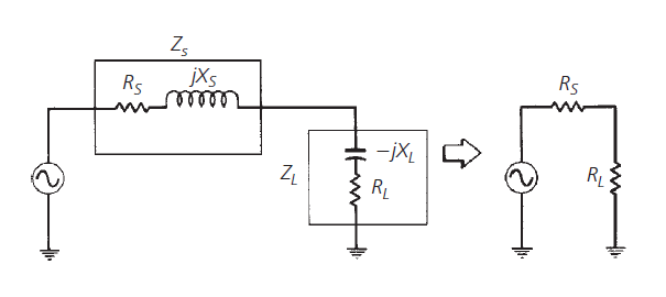
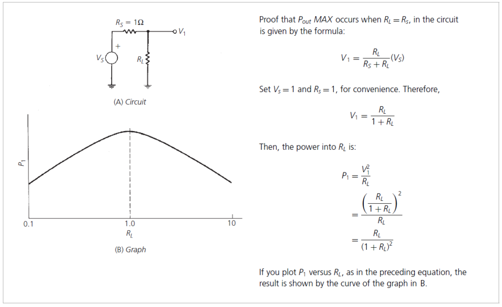
There is a well-known theorem which states that, for DC circuits, maximum power will be transferred from a source to its load if the load resistance equals the source resistance. A simple proof of this theorem is given by the calculations and the sketches shown in the Fig. In the calculation, for convenience, the source is normalized for a resistance of one ohm and a source voltage of one volt. In dealing with AC or time-varying waveforms, however, that same theorem states that the maximum transfer of power, from a source to its load, occurs when the load impedance (ZL) is equal to the complex conjugate of the source impedance. Complex conjugate simply refers to a complex impedance having the same real part with an opposite reactance. Thus, if the source impedance were Zs =R+jX, then its complex conjugate would
be Zs =R−jX.